Indwelling needle device

a technology of indwelling needles and needles, which is applied in the direction of guide needles, catheters, infusion needles, etc., can solve the problems of low possibility of extant soft outer needles injuring the blood vessel of patients, and injuring the blood vessel, etc., and achieves the effect of quick and efficient operation

Active Publication Date: 2016-02-23
JMS CO LTD
View PDF25 Cites 11 Cited by
  • Summary
  • Abstract
  • Description
  • Claims
  • Application Information

AI Technical Summary

Benefits of technology

[0018]According to the present invention, the base portion includes the roof portion and the pair of grasping portions, and, thus, after the puncture with the indwelling needle device, the tube can be pulled together with the stopper by gripping the base portion and pulling the stopper out of the shield. Accordingly, the possibility of an operational error in which the operator pulls out only the stopper and forgets to house the inner needle within the shield can be reduced.
[0019]Furthermore, when puncture with the indwelling needle device has been performed in a state in which the base portion is gripped, the inner needle can be housed within the shield after the puncture, without changing the grip position. Accordingly, a series of operations when using the indwelling needle device can be performed quickly and efficiently.

Problems solved by technology

In such treatments, leaving a metal needle inside a blood vessel may injure the blood vessel.
The possibility of the extant soft outer needle injuring the blood vessel of the patient is low.

Method used


Image

  • Indwelling needle device
  • Indwelling needle device
  • Indwelling needle device

Examples


embodiment 1

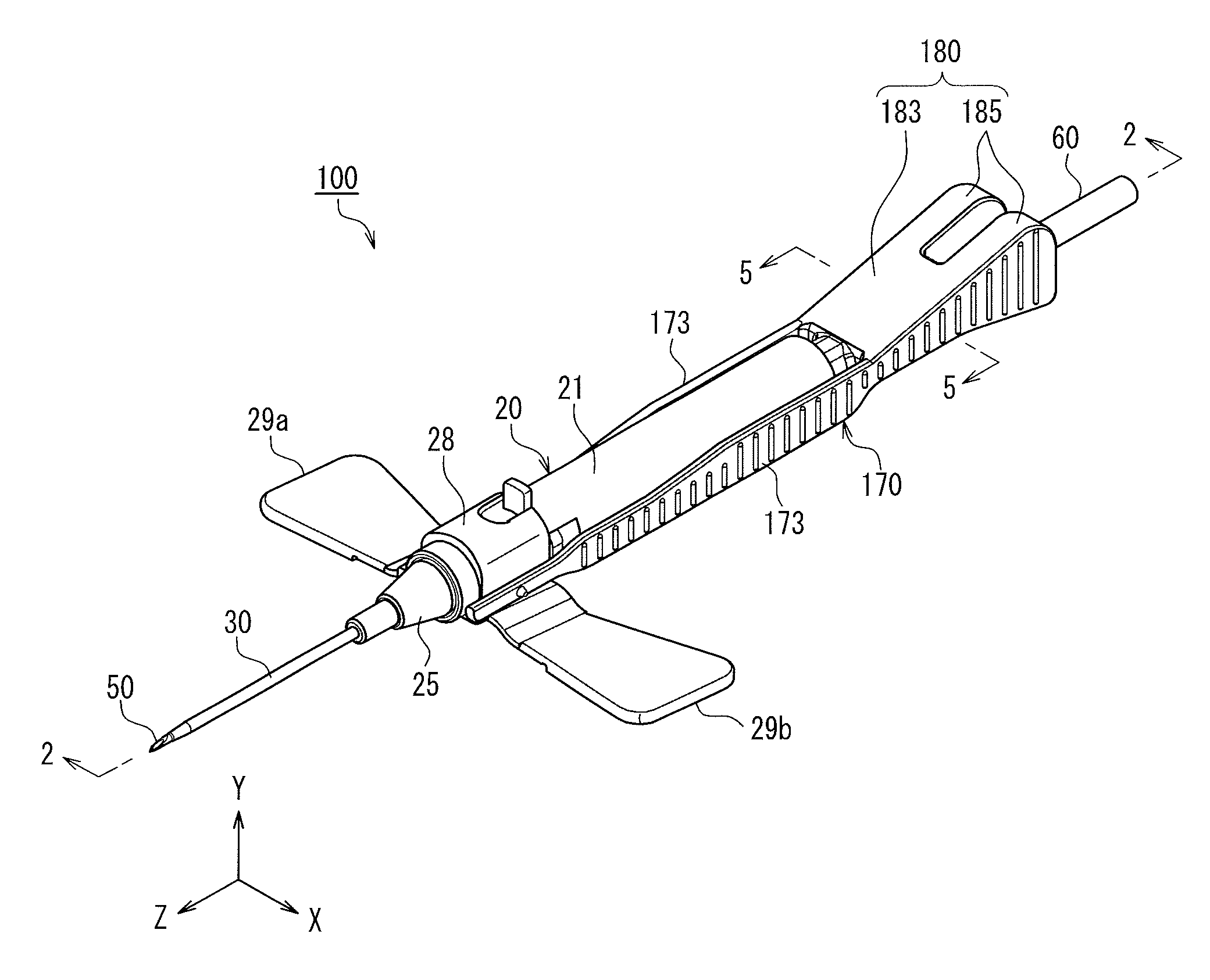
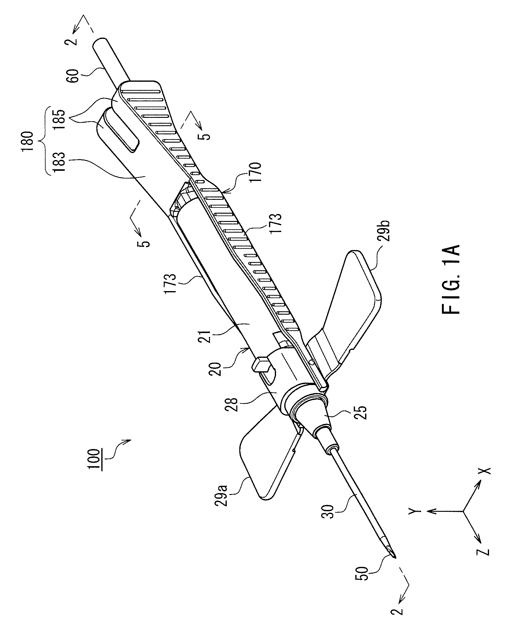
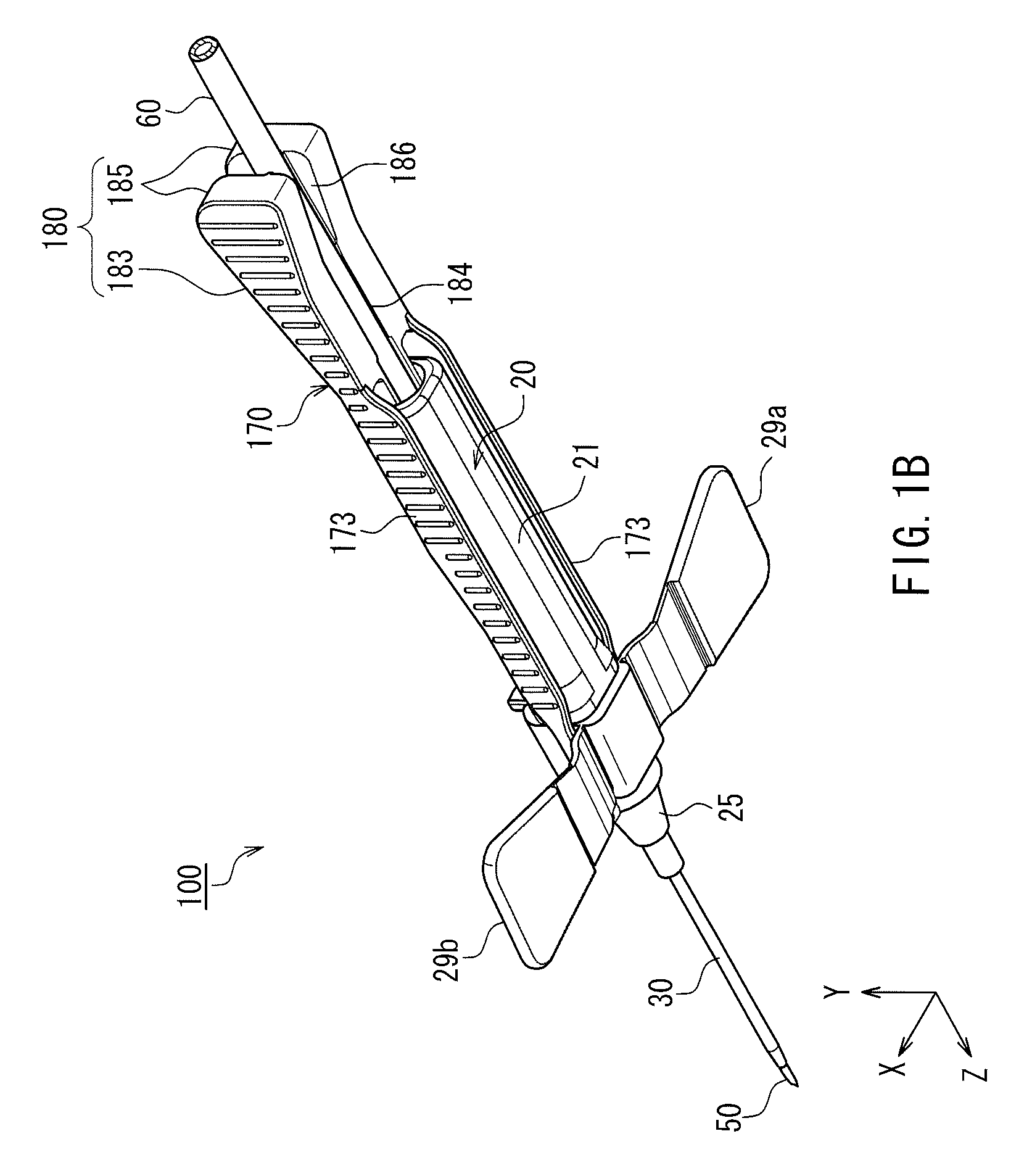
[0054]FIG. 1A is a perspective view, as seen from above, of an indwelling needle device 100 according to Embodiment 1 of the present invention with a hub being at the initial position, and FIG. 1B is a perspective view thereof as seen from below. For the sake of convenience of description, an orthogonal coordinate system is set in which the longitudinal direction of the indwelling needle device 100 is taken as a Z axis, and the horizontal axis and the vertical axis orthogonal to the Z axis are respectively taken as an X axis and a Y axis. Furthermore, a side in the direction of the Y axis arrow (i.e., the upper side in FIGS. 1A and 1B) is referred to as an “upper side”, and a side that is opposite from this side is referred to as a “lower side”. Note that the “horizontal direction” and the “vertical direction” do not refer to the actual orientations when using the indwelling needle device 100. Moreover, a side that is inserted into the patient (a side in the direction of the Z axis ...

embodiment 2

[0096]An indwelling needle device 200 of Embodiment 2 is different from the indwelling needle device 100 of Embodiment 1 in the configuration of the stopper. In the drawings used in the description below, the same constituent members as those in the indwelling needle device 100 of Embodiment 1 are denoted by the same reference numerals, and a description thereof has been omitted. Hereinafter, the indwelling needle device 200 of Embodiment 2 will be described mainly regarding aspects different from those in Embodiment 1.

[0097]FIG. 9A is a perspective view, as seen from above, of the indwelling needle device 200 according to Embodiment 2 of the present invention with the hub 40 being at the initial position, and FIG. 9B is a perspective view thereof as seen from below. FIG. 10 is a cross-sectional view of the indwelling needle device 200 taken along a vertical plane (YZ plane) containing line 10-10 in FIG. 9A and seen in the direction of arrows 10. In Embodiment 2, in order to positio...

embodiment 3

[0113]An indwelling needle device 300 of Embodiment 3 is different from the indwelling needle device 100 of Embodiment 1 in the configuration of the stopper. In the drawings used in the description below, the same constituent members as those in the indwelling needle device 100 of Embodiment 1 are denoted by the same reference numerals, and a description thereof has been omitted. Hereinafter, the indwelling needle device 300 of Embodiment 3 will be described mainly regarding aspects different from those in Embodiment 1.

[0114]FIG. 14A is a perspective view, as seen from above, of the indwelling needle device 300 according to Embodiment 3 of the present invention with the hub 40 being at the initial position, and FIG. 14B is a perspective view thereof as seen from below. FIG. 15 is a cross-sectional view of the indwelling needle device 300 taken along a vertical plane (YZ plane) containing line 15-15 in FIG. 14A and seen in the direction of arrows 15. In Embodiment 3, in order to posi...


PUM


Abstract

A hub can be displaced between an initial position at which the hub is located on a front end side of an inner cavity of a shield and an inner needle penetrates an outer needle and a retracted position at which the hub is located on a rear end side of the inner cavity of the shield and the inner needle is housed within the inner cavity of the shield. A stopper includes an insertion portion that is inserted into the inner cavity of the shield and a base portion that is located on a rear end of the insertion portion. The base portion includes a roof portion that exposes part of an outer circumferential face of a tube connected to the hub and covers the remainder thereof, and a pair of grasping portions that are arranged to sandwich the tube and can be elastically displaced so as to grip the tube.

Description

TECHNICAL FIELD[0001]The present invention relates to an indwelling needle device that includes a soft outer needle and a hard inner needle, and that is configured such that it can be inserted into a patient in a state in which a leading end of the inner needle protrudes from a leading end of the outer needle and then the inner needle can be retracted from the outer needle.BACKGROUND ART[0002]Indwelling needle devices are widely used for such treatments as infusion, blood transfusion, and extracorporeal blood circulation. In such treatments, leaving a metal needle inside a blood vessel may injure the blood vessel. Thus, indwelling needle devices are known that include a soft outer needle and a hard inner needle. The outer needle and the inner needle are inserted into a blood vessel of a patient in a state in which a leading end of the inner needle protrudes from a leading end of the outer needle, and then the inner needle is retracted from the outer needle, so that only the outer ne...

Claims


Application Information

Patent Timeline
Patent Type & Authority Patents(United States)
IPC IPC(8): A61M25/06A61M5/158
CPCA61M5/158A61M25/0606A61M25/0631A61M25/0637A61M2005/1587
Inventor ITO, TORU
Owner JMS CO LTD
Why Eureka
Try Eureka