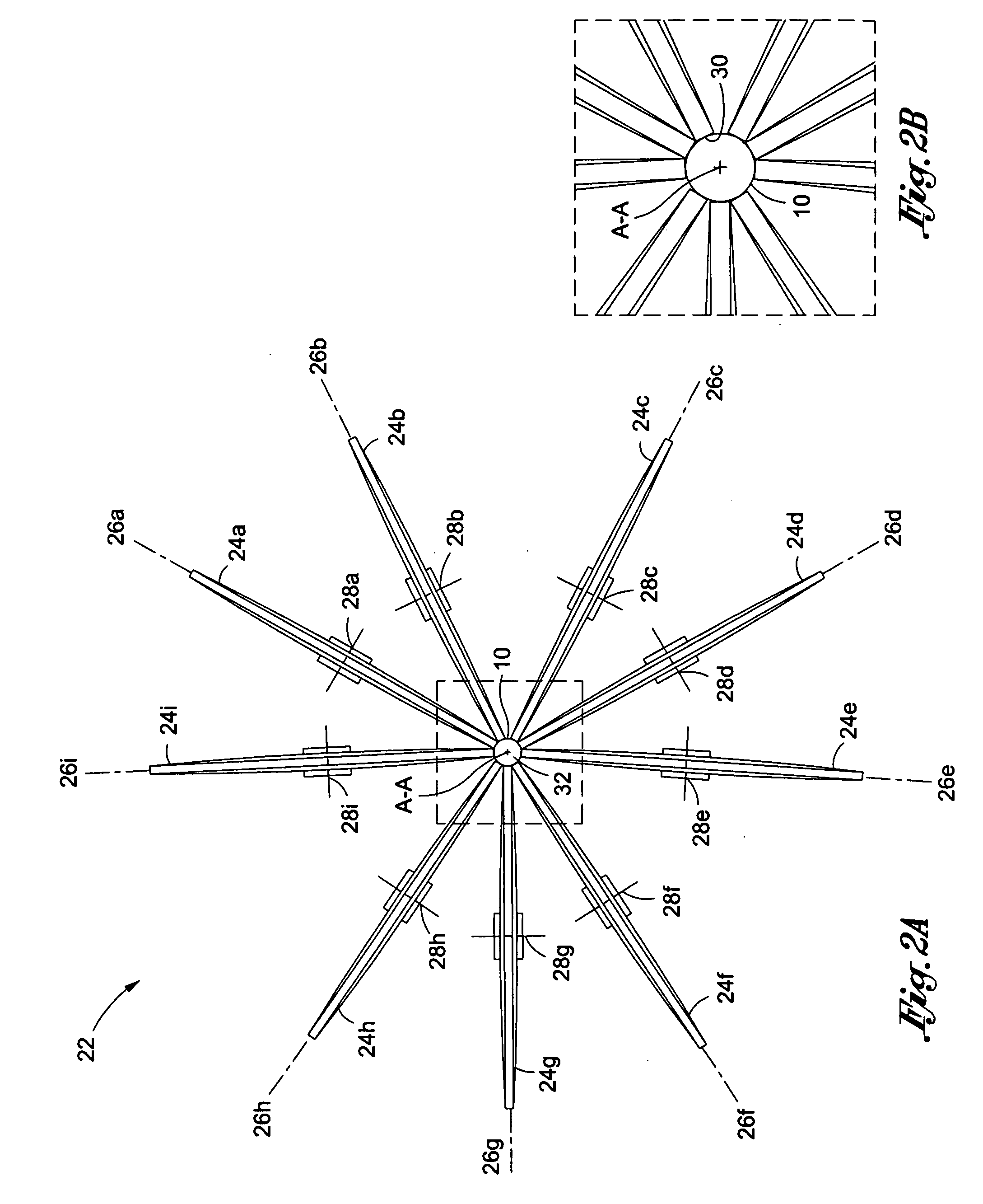
[0013]More precisely, the present invention is directed to a tool for crimping a prosthesis onto a catheter comprising a plurality of wheels, wherein each wheel is rotatably mounted on an axle. Each wheel has an outer circumferential surface configured to apply a radially inward force on the prosthesis. The wheels are mounted so as to be positionable in relation to each other such that a
diameter of each wheel radiates outwardly from a central axis, wherein the outer circumferential surfaces of the wheels are positionable
equidistant from the axis by a first smallest possible distance to define a first space that includes the axis. This configuration permits a prosthesis to be passed between the wheels which in apply a radially inward force on the prosthesis to
crimp the prosthesis to a smaller
diameter. A first number out of the plurality of wheels are mounted so as to be restrained from further advancing toward the axis, thereby leaving a number of remaining wheels mounted to be capable of further advancing toward the axis, wherein the outer circumferential surfaces of the remaining wheels are positionable
equidistant from the axis by a second smallest possible distance to define a second space that includes the axis, the second space being smaller than the first space. In this way, the remaining wheels are advantageously positioned to further
crimp the prosthesis to an even smaller diameter, which would otherwise be impossible if the first number of wheels were not configured to be restrained from further advancing toward the axis.
[0014]In another aspect, the invention includes a method of crimping a prosthesis having an elongate axis. The method comprises positioning a plurality of wheels about the prosthesis so that an outer circumferential surface of each wheel is in contact with the prosthesis; moving the prosthesis along the elongate axis; rotating each of the wheels while maintaining contact between the wheels and the prosthesis, thereby reducing the diameter of the prosthesis; causing a first number of the wheels to no longer be in contact with the prosthesis to leave a first remainder of wheels in contact with the prosthesis; and rotating each of the first remainder of wheels while maintaining contact between each of the first remaining wheels and the prosthesis, thereby further reducing the diameter of the prosthesis. This method has a similar
advantage to the foregoing apparatus, of sequentially crimping the prosthesis to a final diameter, using a first number of wheels and then subsequently a second smaller number of wheels to finish off the crimping to the desired final diameter.
[0016]And in yet a further aspect, the invention includes a method of crimping a prosthesis having an elongate axis. The method comprises positioning a first plurality of wheels about the prosthesis so that an outer circumferential surface of each wheel is in contact with the prosthesis, each surface having a first width; moving the prosthesis along the elongate axis; rotating each of the wheels while maintaining contact between the wheels and the prosthesis, thereby reducing the diameter of the prosthesis. Then, removing all of the first plurality of wheels from being in contact with the prosthesis; positioning a second plurality of wheels about the prosthesis so that an outer circumferential surface of each of the second plurality is in contact with the prosthesis, each surface having a second width less than the first width; moving the prosthesis along the elongate axis; rotating each of the second plurality of wheels while maintaining contact between the second plurality of wheels and the prosthesis, thereby further reducing the diameter of the prosthesis.
[0017]An even further aspect of the invention includes a
system for crimping a prosthesis comprising a first plurality of wheels, wherein each wheel is rotatably mounted on an axle, and each axle of the first plurality lies in the same first plane. Each wheel has an outer circumferential surface and the wheels are positioned in relation to each other such that a diameter of each wheel radiates outwardly from a central axis, whereby the outer circumferential surfaces of the wheels define a first space that includes the central axis, the first space being configured to receive the prosthesis during crimping. A second plurality of wheels is provided wherein each wheel is rotatably mounted on an axle, and each axle of the second plurality lies in the same second plane, the second plane being spaced apart from the first plane by a distance. Each wheel has an outer circumferential surface and the wheels are positioned in relation to each other such that a diameter of each wheel radiates outwardly from the central axis, whereby the outer circumferential surfaces of the wheels define a second space that includes the central axis, the second space being configured to receive the prosthesis during crimping. Significantly, the first space is larger than the second space. By this structure, a prosthesis may advantageously be crimped when the prosthesis is unusually long. The spaced apart sets of wheels allow for greater control over the crimping process as the prosthesis passes from one set to the next.
[0018]Finally, the invention includes a method of crimping a prosthesis having an elongate axis comprising moving the prosthesis along its axis between a first plurality of wheels so that an outer circumferential surface of each of the first plurality of wheels is in contact with the prosthesis; rotating each of the wheels while maintaining contact between the wheels and the prosthesis, thereby reducing the diameter of the prosthesis by a first amount; passing the prosthesis from between the first plurality of wheels to between a second plurality of wheels, the second plurality of wheels being situated adjacent the first plurality; moving the prosthesis between the second plurality of wheels so that an outer circumferential surface of each of the second plurality of wheels is in contact with the prosthesis; rotating each of the second plurality of wheels while maintaining contact between the wheels and the prosthesis, thereby further reducing the diameter of the prosthesis by a second amount. In this embodiment, the invention has advantages similar to those of the previously described embodiment, in which a long prosthesis may be crimped under improved control of one set of wheels adjacent a second set of wheels.
[0019]The present invention is thus capable of homogeneously and precisely crimping a stent onto a
balloon catheter. Such a crimping tool is highly useful to cardiologists and radiologists, for example. Such physicians are constantly concerned with proper deployment of the stent within the patient that it is desirable to have a consistently and reliably crimped stent. The present invention tool is further a time saver, because the stent crimping procedure can be performed fairly efficiently and quickly. Indeed, these and other advantages of the present invention will become apparent from the following detailed description thereof when taken in conjunction with the accompanying exemplary drawings.

