Solar Power Generation Assembly and Method for Providing Same

a technology of solar power generation and assembly, applied in the direction of identification means, lighting and heating apparatus, instruments, etc., can solve the problems of limited sight lines from beneath the structure, difficulty in deployment on parking lots that are not ideally geographically oriented, and avalanche of snow, so as to achieve the effect of high energy yield, wide-spread adoption of solar technology, and highest value and efficiency

Active Publication Date: 2010-01-07
TOTALENERGIES ONETECH
View PDF69 Cites 61 Cited by
  • Summary
  • Abstract
  • Description
  • Claims
  • Application Information

AI Technical Summary

Benefits of technology

[0010]It is an object of the invention to provide the highest value and most efficient use of solar power generation systems by addressing the need for systems which provide multiple economic and public benefits (e.g., high energy yields, shading, alternative fuel stations, charging stations, outdoor seating, WiFi, electrical outlets, lighting, media placement and other potential revenue sources, public awareness). It is therefore desirable to create multifunctional solar power systems, which also provide most, if not all of the aforementioned benefits, and may also impact the wide-spread adoption of solar technology by making its installation attractive, simpler, and more accessible to a larger segment of the potential market.
[0011]Another object of the invention is to reduce light pollution.
[0014]In accomplishing the foregoing and related objects the invention provides an improved solar generation assembly and method of providing same, which combines high energy production, an aesthetically pleasing design, protection from the elements, water reclamation, media placement and a plurality of other benefits / features.
[0015]The novel system comprises a dual-inclination support structure and an array of photovoltaic module assemblies mounted on the structure, which can achieve high energy yields over a wide range of azimuths / orientations. Specifically, the individual canopy wings of the dual-incline structure can differ in length, width, angle of inclination, structural material and solar module or other material mounted on the surface. The canopy wings may also be pivoted or hinged to enhance the energy generation and / or the other functional benefits of the assembly or system. Furthermore, the improved dual-incline support system is modular and may be assembled in a variety of patterns or in a long continuous configuration in which the inclination, width and tilt of the canopy wings may vary over a long linear distance to maintain substantially consistent energy yields as the system orientation changes (e.g., along a highway).
[0016]Present invention differs from prior art because of its dual-incline structure and its multiple uses—including advertising, rainwater / precipitation and snow collection, energy transmission, and ability to place the solar cells at different angles to improve yields.
[0017]In the preferred form the support structure has a decking surface that both conceals and protects the wiring assembly and collects rainwater / precipitation by channeling water which falls through spacings between or around the modules to a gutter or drain. A space exists between the decking surface and the solar module array that allows for air ventilation for the modules and housing for electrical wiring, electrical components and / or transmission lines (e.g. high voltage electrical, cable, fiber optic). This space is enhanced when the decking surface is mounted below the purlins.

Problems solved by technology

Several drawbacks of these structures are limited sight lines from beneath the structures, avalanching of snow and ice from the system, and difficulty of deployment on parking lots that are not ideally geographically oriented.
Many arrangements have been proposed, but in general the currently available support structures for solar power generation do not integrate a high level of design aesthetics with multi-functionality and safety features.

Method used


Image

  • Solar Power Generation Assembly and Method for Providing Same
  • Solar Power Generation Assembly and Method for Providing Same
  • Solar Power Generation Assembly and Method for Providing Same

Examples


Embodiment Construction

[0039]Reference will now be made in detail to several embodiments of the invention that are illustrated in the accompanying drawings. Wherever possible, same or similar reference numerals are used in the drawings and the description to refer to the same or like parts or steps. The drawings are in simplified form and are not to precise scale. For purposes of convenience and clarity only, directional terms, such as top, bottom, up, down, over, above, and below may be used with respect to the drawings. These and similar directional terms should not be construed to limit the scope of the invention in any manner. The words “connect,”“couple,” and similar terms with their inflectional morphemes do not necessarily denote direct and immediate connections, but may also include connections through mediate elements or devices.

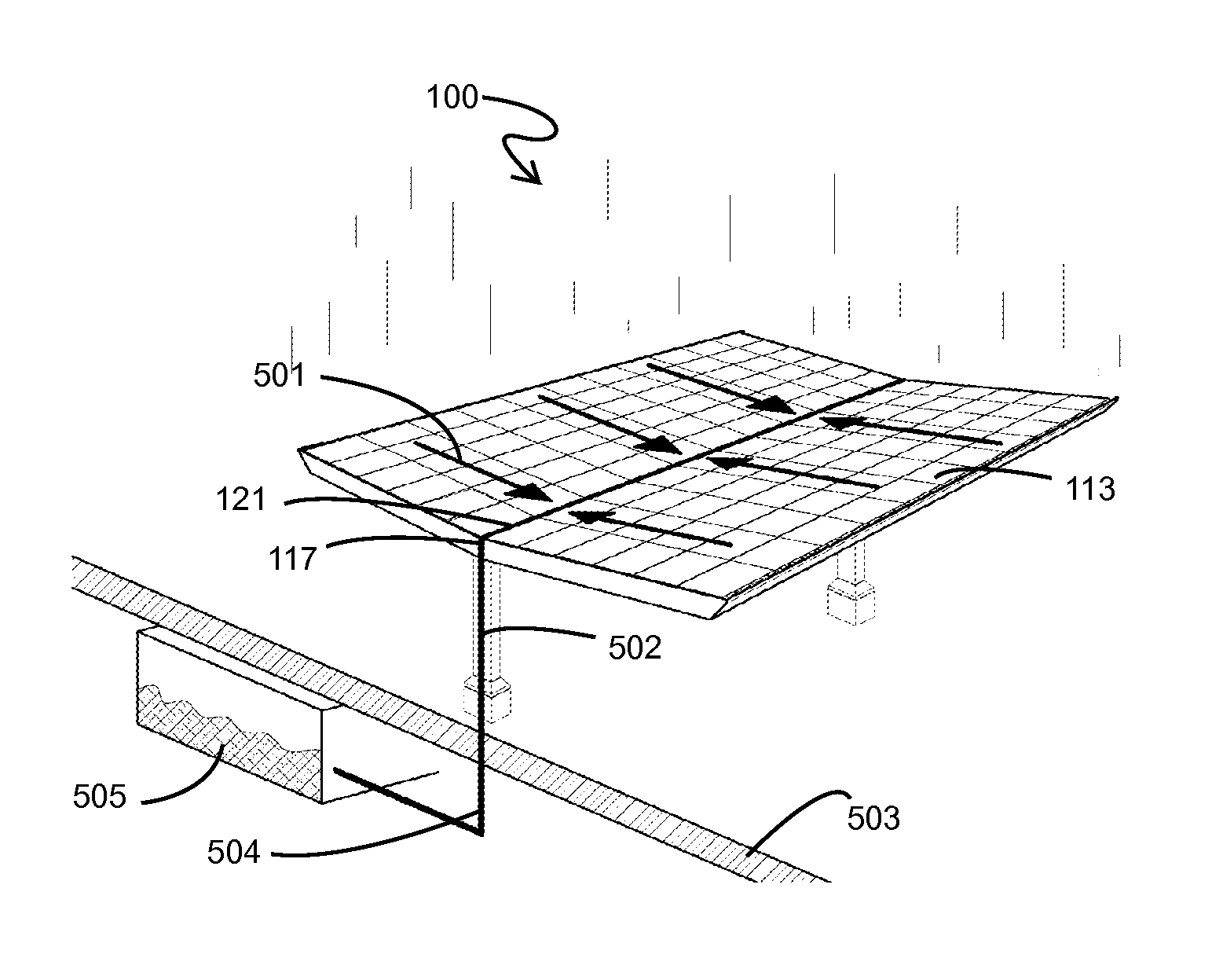
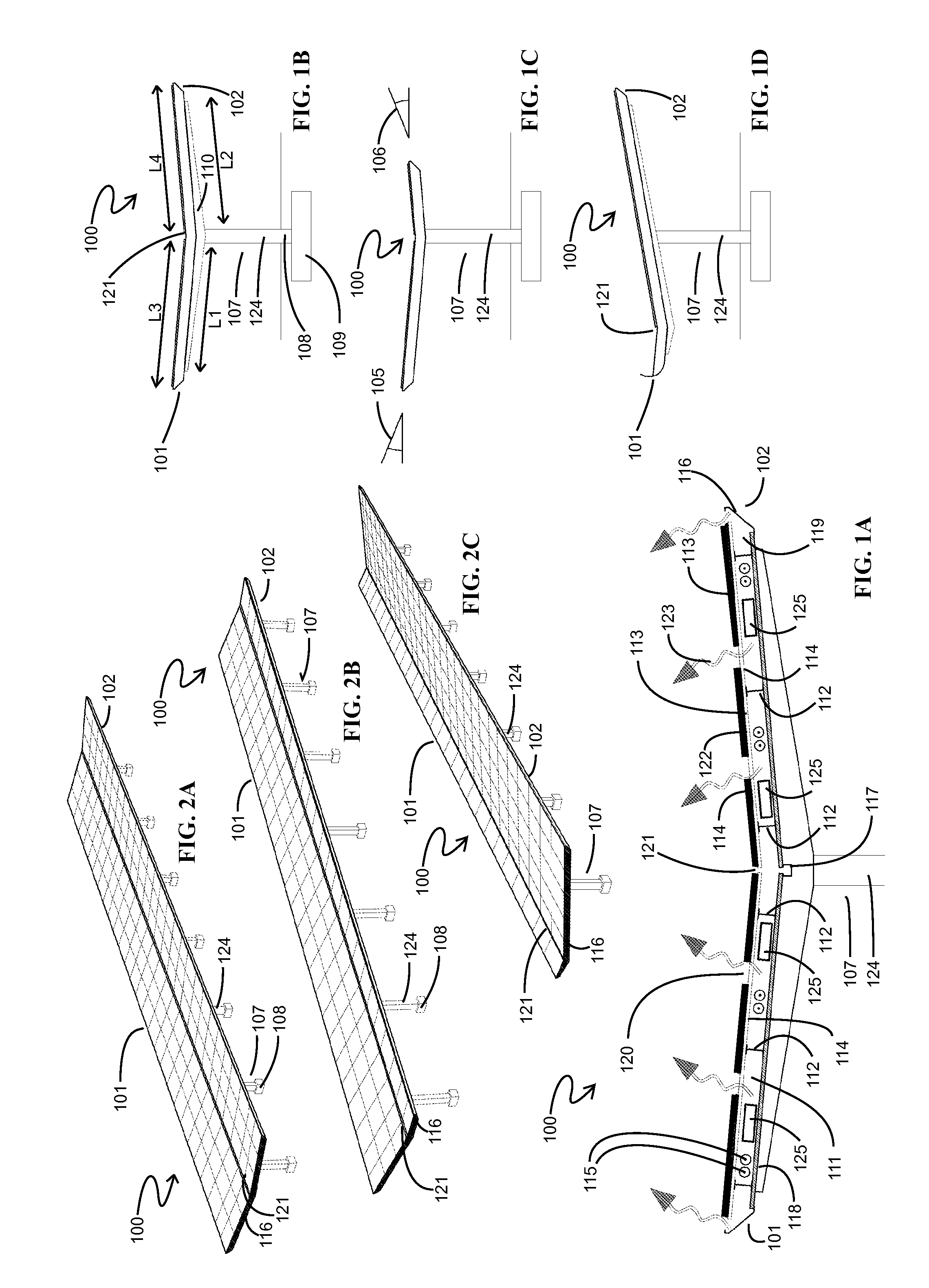
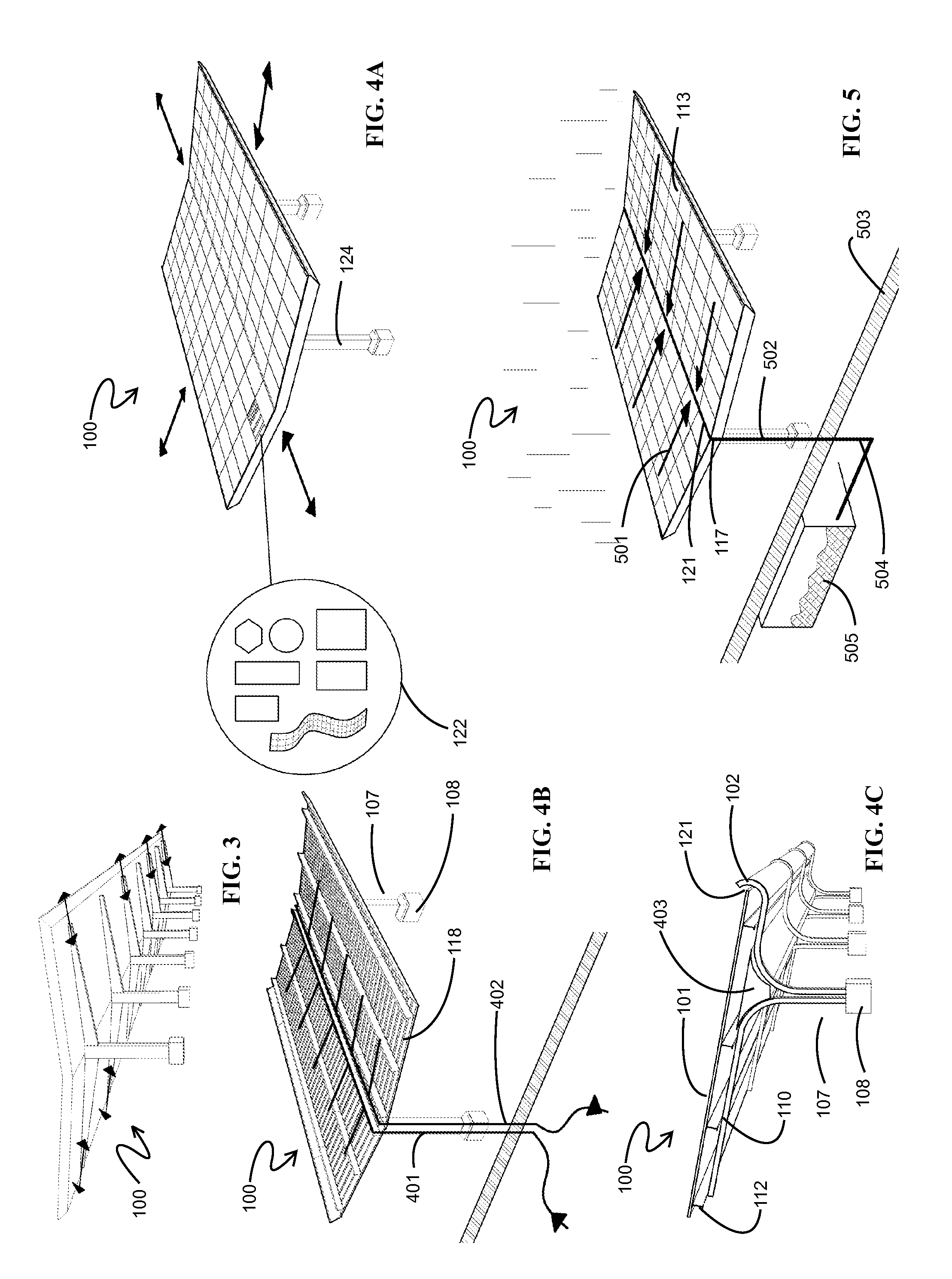
[0040]FIGS. 1A, 1B, 1C, 1D, 2A, 2B and 2C illustrate the basic components of a solar power generating assembly or system 100 that is the subject of the invention. Solar p...


PUM

PropertyMeasurementUnit
incline angleaaaaaaaaaa
angleaaaaaaaaaa
energyaaaaaaaaaa

Abstract

The present invention relates to a solar power generation assembly and method for providing same involving an array of solar generating modules on a dual-incline structure, which can achieve high energy yields over a wide range of azimuths / orientations. The assembly consists of canopy wings providing for the dual-incline structure, where, depending on specifications, the canopy wings can differ in length, width, angle of inclination, structural material and solar module or other material mounted on the surface. The canopy wings may be pivoted or hinged to enhance the energy generation and / or other functional benefits of the assembly or system, including display elements, advertising, rainwater / precipitation and snow drainage and collection and energy transmission. The assembly or system is modular and may be assembled in a long continuous configuration in which the inclination, width and tilt of the canopy wings may vary of a long distance to maintain substantially consistent energy yields as the assembly or system orientation changes.

Description

RELATED APPLICATIONS[0001]This application claims priority to U.S. Provisional Application Ser. No. 61 / 077,851, filed Jul. 2, 2008, entitled “ADVERTISING AND PROMOTIONAL SYSTEM INVOLVING SOLAR ARRAYS AND VISUAL INDICIA AND METHODS FOR MANUFACTURING THE SAME,” which is incorporated herein by reference. This application is also related to PCT Application No. ______, entitled “SOLAR POWER GENERATION ASSEMBLY AND METHOD FOR PROVIDING SAME,” filed on the same day as this application.BACKGROUND OF THE INVENTION[0002]1. Field of the Invention[0003]The present invention relates to a solar power generation assembly and methods for providing same. Specifically, the present invention relates to a solar power generation assembly and method for providing same involving an array of solar generation modules on a dual-incline structure, which can achieve high energy yields over a wide range of azimuths / orientations. The assembly consists of canopy wings providing for the dual-incline structure, whe...

Claims


Application Information

Patent Timeline
Patent Type & Authority Applications(United States)
IPC IPC(8): H01L31/052H01L31/042F24S20/30
CPCG09F11/025G09F17/00G09F19/14G09F19/22Y10T29/49826Y10S362/812Y02E10/47F24J2/523G09F27/007H02S50/10H02S20/10F24S25/10Y02E10/50H01L31/02H02S40/32H02S50/00H02S20/30G09F23/00
Inventor MACKLER, LAURENCE
Owner TOTALENERGIES ONETECH
Why Eureka
Try Eureka