Surface shape measurement apparatus, surface shape measurement method, surface state graphic apparatus

a technology of surface shape and measurement method, applied in the direction of instruments, image data processing, image enhancement, etc., can solve the problems of difficult for the conventional system to plot images precisely, the equipment cost is high, and it takes a significant time and effort for a person to measure patterns and make sketches, and achieves a wide range of surface shapes.

Inactive Publication Date: 2007-04-17
KK TOPCON
View PDF18 Cites 61 Cited by
  • Summary
  • Abstract
  • Description
  • Claims
  • Application Information

AI Technical Summary

Benefits of technology

[0037]In an apparatus constituted as described above, the measuring object 1 is placed in a position to be photographed by the stereo-photographing part 3, and at least two stereo-photographing units constituting the stereo-photographing part 3 photographs the measuring object 1 in stereo from a plurality of directions. Each of the stereo-photographing units has right and left imaging devices 3R and 3L for photographing the measuring object 1 in stereo. Since the measuring object 1 is photographed in stereo from a plurality of directions, a wider range of surface shape of the object 1 can be measured than when it is photographed from one direction. Since the stereo-photographing parameters in specified photographing directions are stored in advance, the surface shape can be precisely measured even if the object 1 and the stereo-photographing unit 90 are not positioned precisely. Further, since the stereo-photographing part 3 has at least two stereo-photogra

Problems solved by technology

However, the equipment cost is high to measure the surface shape of a trove with a conventional contact or non-contact type measuring instrument.
However, it is difficult for the conventional system to plot the images precisely.
More specifically, there are following problems, depending upon the way of measuring.1) It takes significant time and effort for a person to measure the patterns and make a sketch of them.
Also, it is difficult to get high accuracy in dimension and shape.2) In the case of a contact type measuring instrument, it takes long time to trace the surface of a trove as a measuring object.
Thus, the drawing is less accurate in the positional relation of the surface shape or pattern than the measurement data.4) There is a problem common to the above cases 1) to 3).
When the survey takes a long time, the interruption of the work is prolonged and the period of construction is prolonged.
However, such a system has not been widely adopted since it causes a problem regarding privacy of the customers and requires the shops to invest a large a

Method used


Image

  • Surface shape measurement apparatus, surface shape measurement method, surface state graphic apparatus
  • Surface shape measurement apparatus, surface shape measurement method, surface state graphic apparatus
  • Surface shape measurement apparatus, surface shape measurement method, surface state graphic apparatus

Examples


first embodiment

1. First Embodiment

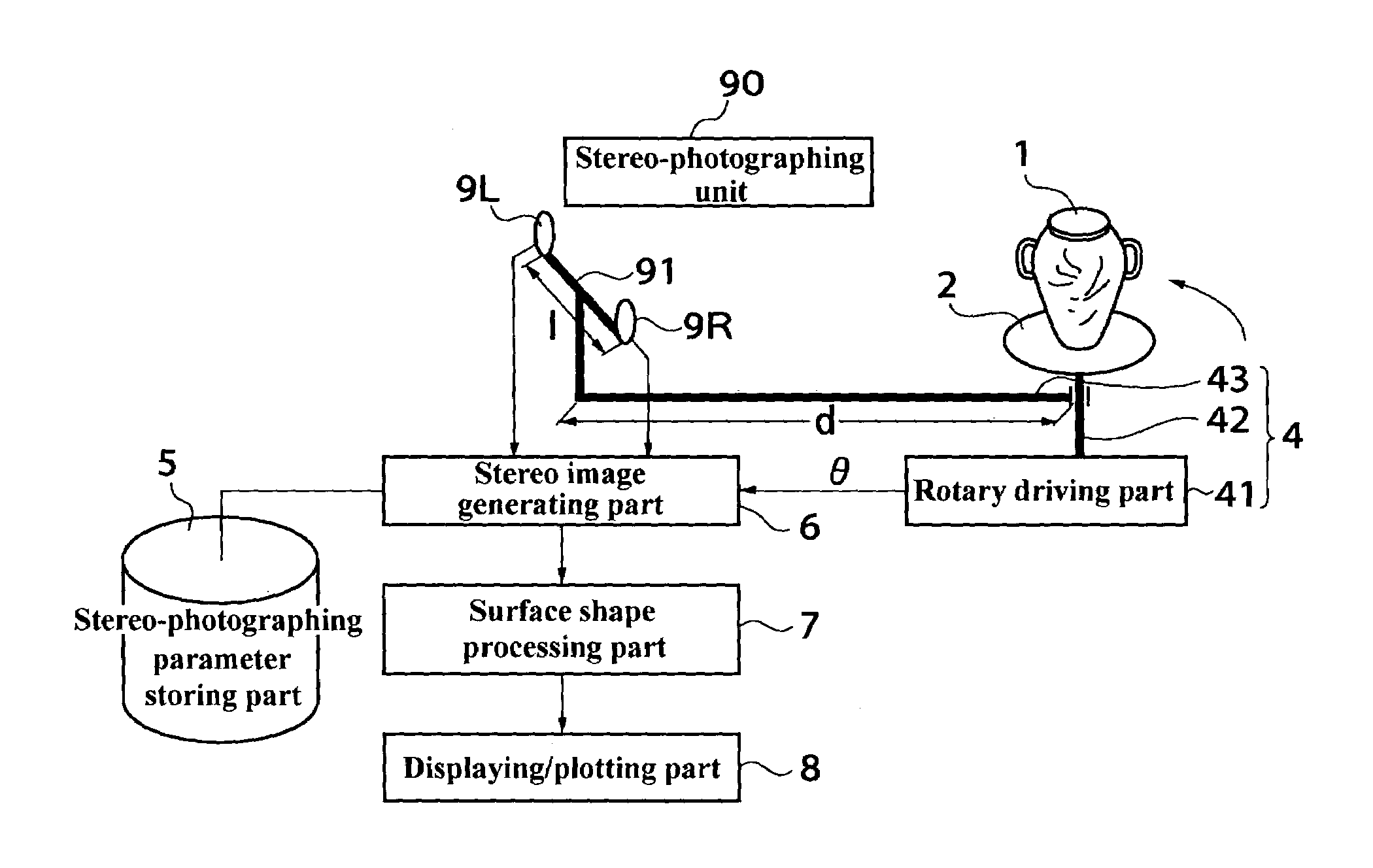
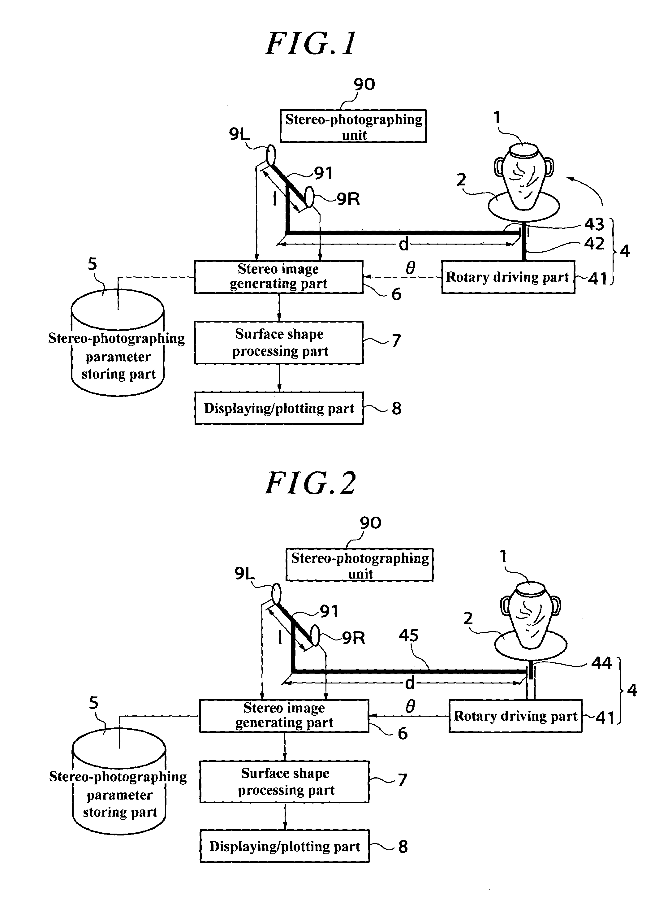
[0111]Description will be hereinafter made of this invention with reference to the drawings. FIG. 1 is a block diagram illustrating the structure of a first embodiment of this invention. In the drawing, a measuring object 1 is an object having a surface shape or surface pattern to be three-dimensionally measured in a non-contact manner such as a trove, human body, vehicle, or machine structure. A table 2 is a stand to place the measuring object 1 on, and may be a stage. A stereo-photographing unit 90 is a device for photographing the measuring object 1 placed on the table 2 in stereo and comprises two imaging devices 9R and 9L such as CCDs (charged-coupled devices), digital cameras or film-type cameras which are attached to a rod as an imaging device fixing body 91 at a distance l apart from each other. The two imaging devices 9R and 9L are attached to the imaging device fixing body 91 in such a manner that their optical axes are generally parallel to each other a...

second embodiment

2. Second Embodiment

[0175]FIG. 17 is a block diagram illustrating the structure of a second embodiment of this invention. The second embodiment differs from the first embodiment in that a stereo-photographing direction control part 12 and a stereo image storing part 15 are provided. The stereo-photographing direction control part 12 controls the relative position changing part 4 to change the angle θ corresponding to the direction from which the stereo-photographing unit 90 photographs the measuring object 1 so that the stereo-photographing unit 90 can photograph the measuring object 1 from at least three directions to obtain stereo images of the primary peripheral surfaces of the measuring object 1. The stereo-photographing direction control part 12 allows the measurement of a large number of measuring objects 1 to be made with high efficiency. The stereo-photographing control part 12 may be a sequence program registered in a PLC (programmable logic controller) which controls the r...

third embodiment

3. Third Embodiment

[0177]FIG. 18 is a block diagram illustrating the structure of a third embodiment of this invention. The third embodiment differs from the first embodiment in that the function of photographing an object in stereo is accomplished by one imaging device 10 and a stereo-photographing control part 9. The stereo-photographing control part 9 rotates an imaging device connecting rod 46 as the relative position changing part 4 so that the imaging device 10 can photograph the measuring object 1 from stereo-photographing directions consisting of a pair of right and left photographing directions. The imaging device connecting rod 46 keeps the distance d between the table 2 and the imaging device 10 constant and is driven by the rotary driving part 41 to move the imaging device 10 by a rotational angle difference Δθ. The distance from the original position of the imaging device 10 to the position a rotational angle difference Δθ away from the original position is the baseline...


PUM


Abstract

A surface shape measuring apparatus, comprising: a stereo-photographing part 3 for photographing an object 1 in stereo; a relative position changing part 4 for changing the positional relation between the stereo-photographing part 3 and the object 1; means 5 for storing stereo-photographing parameters in a plurality of directions from which the stereo-photographing part 3 photographs the object 1; a stereo-image generating means 6 for controlling the stereo-photographing part 3 to photograph the object 1 from the plurality of directions with the stored stereo-photographing parameters and generating stereo images of the object 1; and a surface shape processing means 7 for measuring the surface shape of the object 1 based on the stereo images of the object 1.

Description

TECHNICAL FIELD[0001]This invention relates to an apparatus and a method for three-dimensionally measuring the surface shape or pattern of a trove, human body, vehicle, machine structure or the like in a non-contact manner. This invention also relates to a surface shape plotting apparatus for plotting the surface shape or pattern of a trove or the like measured with the surface shape measuring apparatus.BACKGROUND ART[0002]To measure the surface shape of a trove such as a clay pot, a person makes a sketch of it, measuring it with a ruler or the like, or a contact type measuring instrument which measures the surface shape of the object by tracing the contour of the object is used. A non-contact type measuring instrument which photographs the object using a slit light source or measures the object using a laser beam is also used.[0003]In clothing stores, salespeople measure the body size of customers with tape measures to determine the size of clothing items which suit them best. In t...

Claims


Application Information

Patent Timeline
IPC IPC(8): G01B11/24G01B11/30G01C11/06G06T7/00H04N13/00
CPCG01B11/24G01C11/06G06T7/002G06T7/0075H04N13/0221H04N13/0239H04N13/0242H04N13/0246H04N13/0418G06T2207/10012H04N13/0055H04N2013/0081G01B11/2545G06T7/593G06T7/85H04N13/189H04N13/221H04N13/239H04N13/243H04N13/246H04N13/32
Inventor KOCHI, NOBUOOTANI, HITOSHINIIMURA, SATORU
Owner KK TOPCON
Why Eureka
Try Eureka