Supercharge Your Innovation With Domain-Expert AI Agents!

Plug connector

a plug connector and multi-contact technology, applied in the direction of coupling device connection, coupling contact member, electrical apparatus, etc., can solve the problems of increasing the number of poles, rendering the production of plug connectors between the socket side and the plug side difficult if not impossible, rendering the successful plugging-together process impossible,

Active Publication Date: 2016-02-23
STAUBLI ELECTRICAL CONNECTORS AG
View PDF13 Cites 13 Cited by
  • Summary
  • Abstract
  • Description
  • Claims
  • Application Information

AI Technical Summary

Benefits of technology

[0007]Based on this prior art, an object of the invention is to provide a multiple-contact or rather multi-pole plug connector that overcomes the disadvantages of the prior art. In particular the plug connector is to be produced in a simpler manner and its reliability is to be improved.
[0009]The socket elements and accordingly the plug elements that lie in the region of the wall are protected against mechanical influences by virtue of the arrangement of the wall and the opening, so that the socket elements and accordingly the plug elements cannot bend and as a result it is possible to plug said socket elements and said plug elements together. As a consequence, the reliability is improved.
[0011]In a preferred embodiment, the wall extends from the contact surface of the plug housing and the opening extends from the contact surface of the socket housing into the socket housing. As a consequence, the wall encompasses parts of the plug elements and the socket elements are arranged in the opening. This is a particularly simple configuration.
[0012]The plug elements and accordingly the socket elements when viewed from the contact surface are preferably embodied so as to be shorter than the wall so that the plug elements or accordingly the socket elements do not protrude beyond the wall. It is preferred that the plug elements and accordingly the socket elements when viewed from the base of the opening are embodied so as to be shorter than the depth of the opening from the contact surface to the base, so that the plug elements or the socket elements respectively are arranged entirely in the opening. As a consequence, it is ensured that during the plugging-together process, the socket side is aligned towards the plug side by means of pairing the wall and the opening prior to parts that are responsible for the electrical contact coming into contact with one another, which further increases the reliability.

Problems solved by technology

Experience has shown that problems can occur with an increasing number of poles during the plugging-together process.
In particular, reference is made to the issue of canting that in part renders the production of the plug connector between the socket side and the plug side difficult if not impossible.
The issue of canting can also lead to the electrically conductive elements of the socket side and / or the plug side becoming damaged and therefore rendering a successful plugging-together process impossible.

Method used


Image

  • Plug connector
  • Plug connector
  • Plug connector

Examples


Embodiment Construction

[0007]Based on this prior art, an object of the invention is to provide a multiple-contact or rather multi-pole plug connector that overcomes the disadvantages of the prior art. In particular the plug connector is to be produced in a simpler manner and its reliability is to be improved.

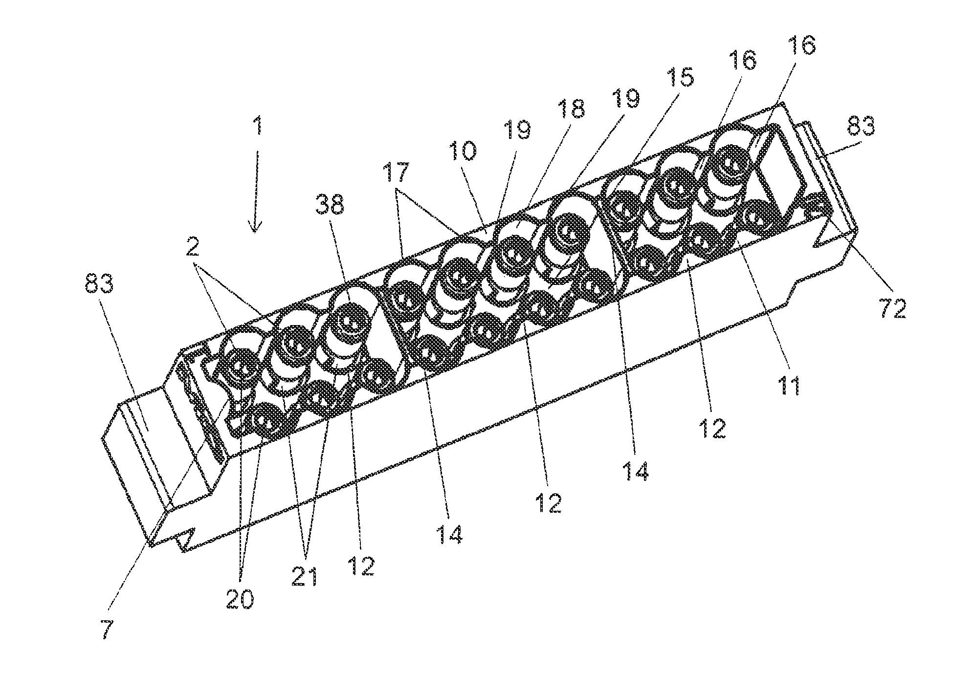
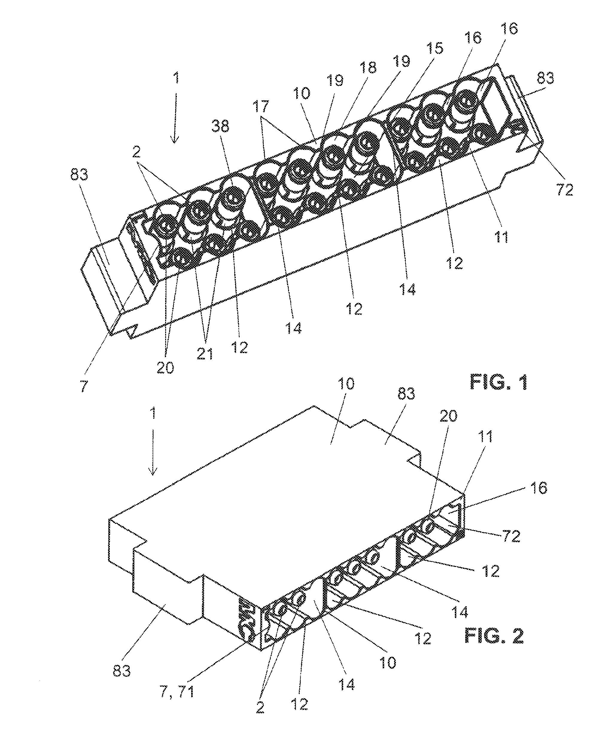
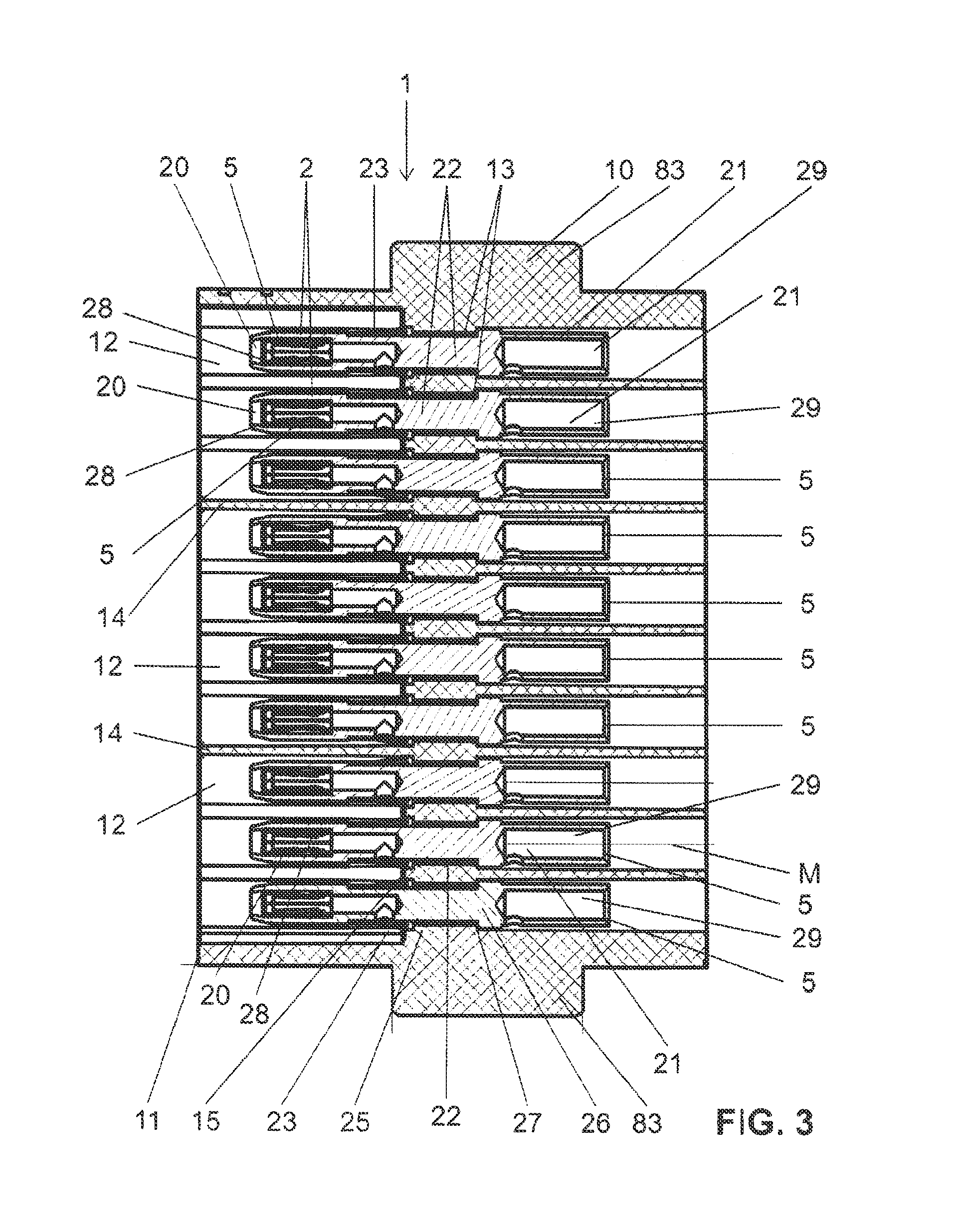
[0008]A multiple-contact plug connector according to claim 1 achieves an object of this type. Accordingly, a releasable multiple-contact plug connector comprises a socket side having an electrically insulating socket housing and having a plurality of socket elements that are received in the socket housing and comprise a socket section and a contact section for the purpose of providing an electrically conductive connection to an external element, in particular to a multi-wire cable, and said releasable multiple-contact plug connector comprises a plug side having an electrically insulating plug housing and having a plurality of plug elements that are received in the plug housing and comprise a pin secti...


PUM


Abstract

The invention relates to a releasable multi-plug connector comprising a socket side (1) with an insulating socket housing (10) and with a plurality of socket elements (2) which are received in the socket housing (10) and which comprise a socket portion (20) and a contact portion (21) for connecting to an external element in an electrically conductive manner, in particular a multipolar cable. The plug connector also comprises a plug side (3) with an insulating plug housing (30) and with a plurality of plug elements (4) which are received in the plug housing (30) and which comprise a pin portion (40) and a contact portion (41) for connecting to an external element in an electrically conductive manner, in particular a multipolar cable. The socket housing (10) and the plug housing (30) can be connected together along a plug direction (S), said pin portions (40) of the plug elements (4) protruding into the socket portions (20) of the socket elements (2) in the plugged state such that an electric contact can be provided between the socket side (1) and the plug side (2) via the socket portion (20) and the pin portion (40). The socket housing (10) and the plug housing (30) have a contact surface (11, 31) via which the socket housing (10) and the plug housing (30) are in contact. A wall (32) extends from the contact surface (31) of the plug housing (30) or the socket housing (10), said wall at least partly surrounding the pin portions (40) or the socket portions (20), and an opening (12) extends from the contact surface (11) that does not have the wall (32) into the socket housing (10) or the plug housing (30), the socket portions (20) or the pin portions (40) lying in said opening (12). The wall (32) cross-section perpendicular to the plug direction matches the opening (12) cross-section perpendicular to the plug direction, and the wall (32) protrudes into the opening (12) in the plugged state.

Description

CROSS REFERENCE TO RELATED APPLICATIONS[0001]This is a National Stage of International Application No. PCT / EP2012 / 067437 filed Sep. 6, 2012, claiming priority based on European Patent Application No. 11 181 039.6 filed Sep. 13, 2011, the contents of all of which are incorporated herein by reference in their entirety.TECHNICAL FIELD[0002]The present invention relates to a multiple-contact plug connector in accordance with the preamble of claim 1.PRIOR ART[0003]Multiple-contact or multi-pole plug connectors that comprise a multiplicity of connections that are arranged parallel to one another are known from the prior art. A multiplicity of electrical connections, in particular electrical connections that have different polarities, can be provided using a single plugging-together process.[0004]By way of example, US 2006 / 0110978 illustrates a plug connector of this type, wherein the individual modules can be mutually connected by way of a dovetail joint.[0005]One system of the applicant ...

Claims


Application Information

Patent Timeline
Patent Type & Authority Patents(United States)
IPC IPC(8): H01R13/10H01R13/64H01R13/629H01R13/645H01R13/04H01R107/00
CPCH01R13/64H01R13/04H01R13/10H01R13/629H01R13/6456H01R2107/00
Inventor BELTZER, PATRICK
Owner STAUBLI ELECTRICAL CONNECTORS AG
Features
  • R&D
  • Intellectual Property
  • Life Sciences
  • Materials
  • Tech Scout
  • Unparalleled Data Quality
  • Higher Quality Content
  • 60% Fewer Hallucinations
Learn More