
Magnetoelectric composites

a technology of magnetostrictive devices and composites, applied in the field of magnetostrictive devices, thin material handling, device material selection, etc., can solve the problem of limitations imposed on actualizing

Active Publication Date: 2016-03-01
KOREA INST OF MATERIALS SCI
View PDF13 Cites 2 Cited by
  • Summary
  • Abstract
  • Description
  • Claims
  • Application Information

AI Technical Summary

Benefits of technology

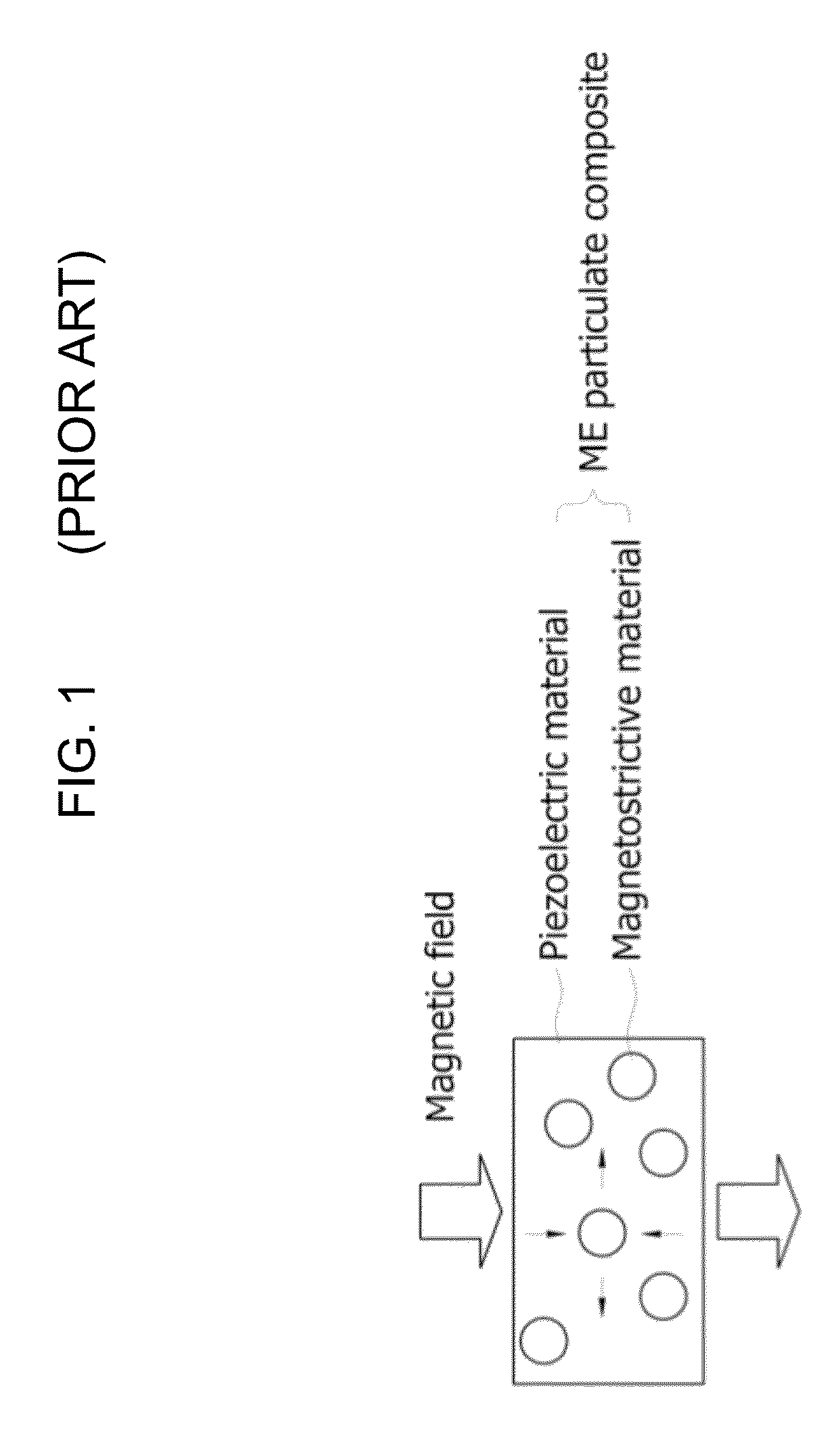
[0016]Materials applicable to such ME composites have been very thoroughly studied over the past ten years, and a composite having a magnetostrictive-piezoelectric-magnetostrictive layered structure is favorable in attaining high ME composites.
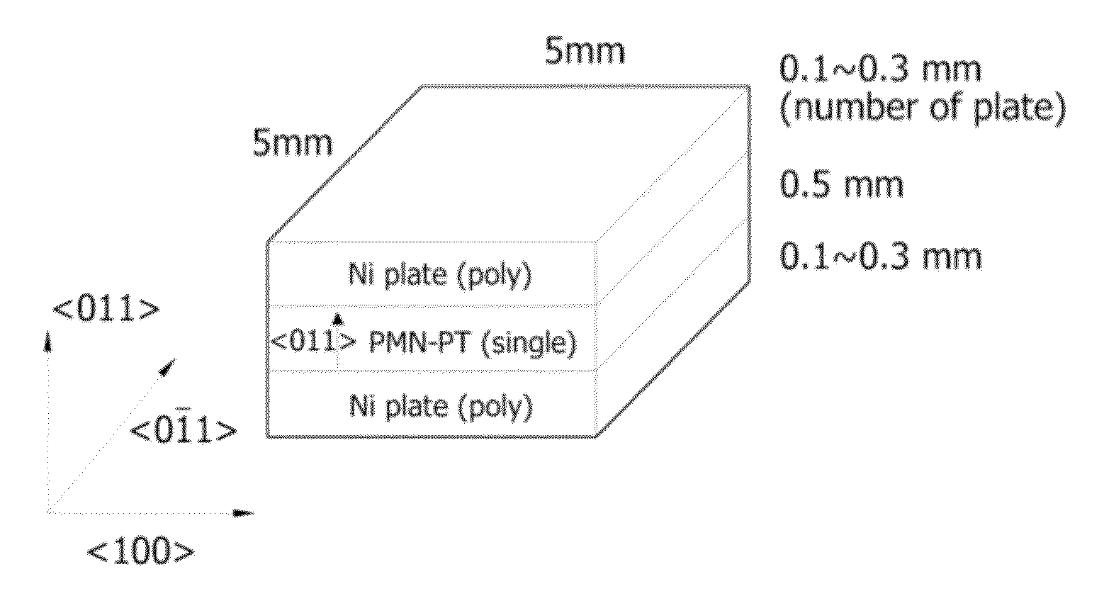
[0018]However, even when ME layered composites are formed using such a giant magnetostrictive material, the maximum magnetoelectric coefficient is conventionally low and thus has to be increased so that they can be applied to actual devices, and thus limitations are imposed on actualizing them. Therefore, the present invention is intended to provide an ME composite which is configured such that piezoelectric single crystals having high piezoelectric properties and a metal magnetostrictive material having a high magnetostrictive coefficient are provided in the form of a layered structure, wherein the orientation of the piezoelectric single crystals is controlled so as to further increase the sensitivity of the ME composite.
[0025]Also, according to the present invention, the frequency of the alternating magnetic field applied to the magnetostrictive material layer may be adjusted, so that a resonance frequency of the piezoelectric material layer becomes variable.
[0037]Also, according to the present invention, when utilizing the maximum ME properties of the ME composite at the antiresonance frequency depending on the frequency of the alternating magnetic field, the ratio between thickness, width and length of the ME composite may be adjusted, so that the resonance-antiresonance frequency range of the composite may be controlled, thereby making it possible to manufacture a device having maximum ME properties at a specific frequency.

Problems solved by technology

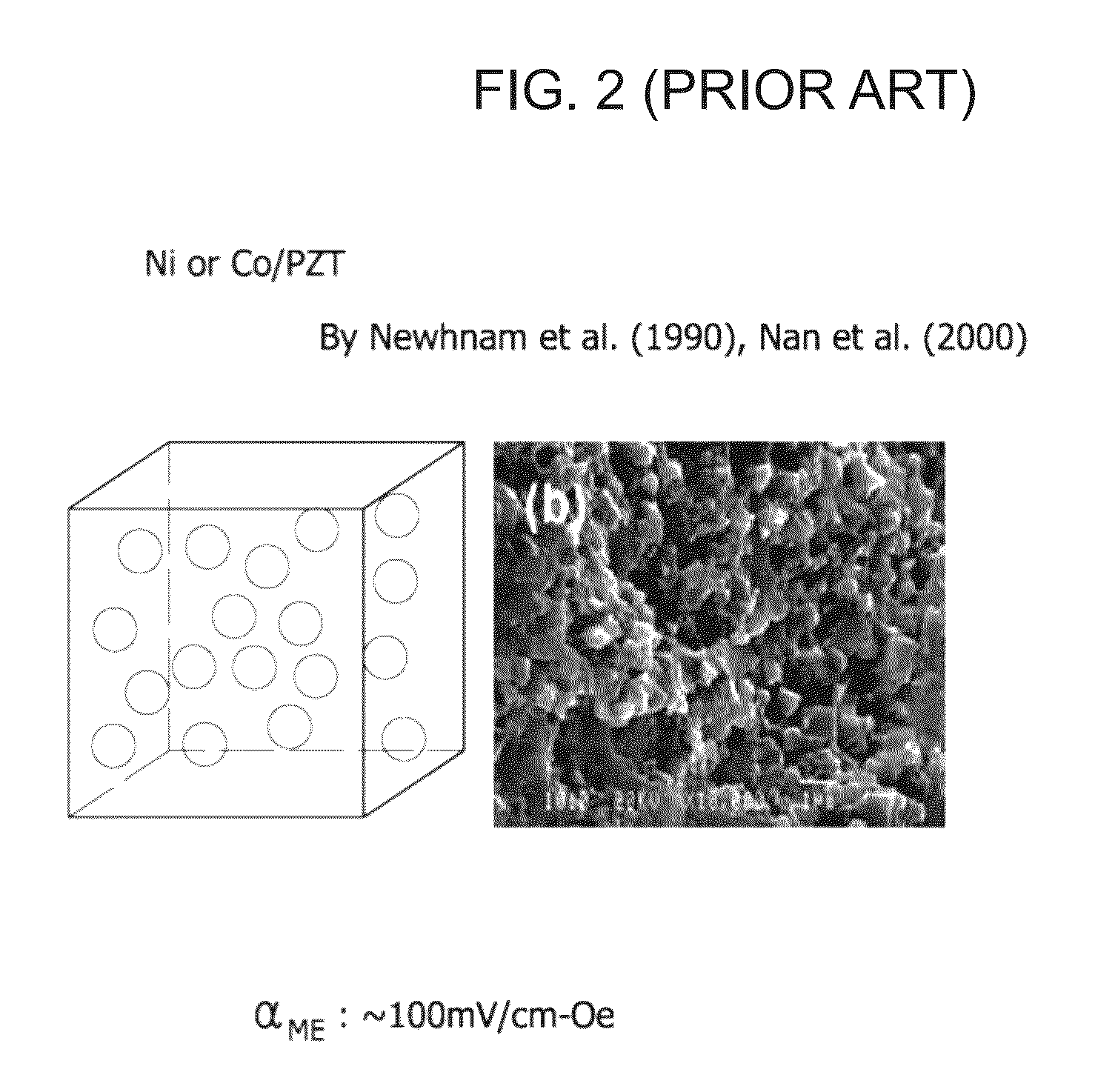
However, even when ME layered composites are formed using such a giant magnetostrictive material, the maximum magnetoelectric coefficient is conventionally low and thus has to be increased so that they can be applied to actual devices, and thus limitations are imposed on actualizing them.

Method used


Image

  • Magnetoelectric composites
  • Magnetoelectric composites
  • Magnetoelectric composites

Examples


Embodiment Construction

[0057]Hereinafter, embodiments of the present invention will be more fully understood with reference to the appended drawings. Throughout the drawings, the same reference numerals are used to refer to the same or similar elements. Furthermore, descriptions of known techniques, even if they are pertinent to the present invention, are regarded as unnecessary and may be omitted when they would make the characteristics of the invention and the description unclear.

[0058]FIG. 5 illustrates the orientation of piezoelectric single crystals according to the present invention.

[0059]A conventional ME composite using piezoelectric single crystals is configured such that, upon layering a magnetostrictive material and a piezoelectric material using an orientation of piezoelectric single crystals, a layered structure in which the orientation is set to a thickness direction of the piezoelectric material is employed, and such an orientation structure uses the piezoelectric constant g31 of the piez...


PUM

PropertyMeasurementUnit
Tcaaaaaaaaaa
Tcaaaaaaaaaa
ferroelectric phase transition temperatureaaaaaaaaaa

Abstract

Disclosed is a magnetoelectric (ME) composite including both a piezoelectric material and a magnetostrictive material, wherein a piezoelectric single crystal material having high piezoelectric properties is used as the piezoelectric material, and a metal magnetostrictive material having high magnetostrictive properties is used as the magnetostrictive material, thus achieving an ME composite having a layered structure via adhesion. When the ME layered composite is manufactured such that a <011> crystal orientation of the piezoelectric single crystal material is set to a thickness direction, high ME voltage coefficient, which is at least doubled, compared to a conventional <001> crystal orientation, can be obtained, and such an effect is further maximized in the resonance of the composite.

Description

[0001]This application claims priority under 35 USC 119 to Korean Patent application No. 10-2012-0029244 filed Mar. 22, 2012, the disclosure of which is incorporated herein by reference.BACKGROUND OF THE INVENTION[0002]1. Field of the Invention[0003]The present invention relates to a magnetoelectric composite and, more particularly, to a layered composite in which the orientation of a piezoelectric material layer is controlled such that a <011> orientation is set to a thickness direction.[0004]2. Description of the Related Art[0005]A magnetoelectric (ME) effect is a material property and is widely found in composite structures comprising magnetostrictive and piezoelectric materials.[0006]The ME effect means that, when any material having properties in response to both a magnetic field and an electric field is exposed to a magnetic field, an electric voltage is generated, whereas when the material is exposed to an electric field, it is magnetized. Thus, in order to impart an ME...

Claims


Application Information

Patent Timeline
Patent Type & Authority Patents(United States)
IPC IPC(8): H01L41/12H01L41/16
CPCH01L41/12H01L41/16Y10T156/10Y10T428/2495Y10T428/31678H10N30/85H10N35/00
Inventor RYU, JUNGHOKIM, JONG-WOOYOON, WOON-HAPARK, DONG-SOO
Owner KOREA INST OF MATERIALS SCI
Learn More