Boost air management for improved engine performance

a technology of engine performance and boost air, which is applied in the direction of machines/engines, mechanical equipment, electric control, etc., can solve the problems of undesirable power lag, torque may not be available, power, fuel efficiency, emissions control performance of a boosted engine may suffer, etc., to achieve greater fuel efficiency, lower emissions, and power. the effect of boosting the engin

Active Publication Date: 2016-03-08
FORD GLOBAL TECH LLC
View PDF32 Cites 8 Cited by
  • Summary
  • Abstract
  • Description
  • Claims
  • Application Information

AI Technical Summary

Benefits of technology

[0005]Thus, at least some of the above issues may be addressed by a method for a turbocharged engine. In one embodiment, the method comprises, in response to a tip-in, reducing turbo lag by discharging pressurized charge from a boost reservoir to an exhaust manifold. In this way, pressurized charge is discharged into the exhaust manifold to rapidly increase exhaust pressure.
[0006]For example, during previous engine operation prior to the tip-in, the boost reservoir may already be filled with primarily combusted exhaust gas from the exhaust manifold. In response to the tip-in, the pressurized charge including the combusted exhaust gas may be discharged into the exhaust manifold. As a result, an exhaust pressure at the turbine may be increased to expedite turbine spool-up. By providing the charge to the exhaust manifold, it can be more easily spread over a longer duration as the turbine consumes the gas at a lower rate than the engine induction. In this way, the increased exhaust pressure can assist in compensating for turbo-lag, and maintain a continuously increasing engine output while responding to the tip-in.

Problems solved by technology

During transient conditions, however, the power, fuel efficiency, and emissions-control performance of a boosted engine may suffer.
Such torque may not be available, however, if the turbine that drives the compressor is not fully spun up.
As a result, an undesirable power lag may occur before the intake air flow builds to the required level.
However, the inventors herein have identified potential issues with such a system.
As one example, if the boost reservoir has a small volume, the boost air may be initially able to supply sufficient air to provide increased desired torque, but after the supply is depleted, such as at higher engine speeds, the turbine may still not be spun up, and thus torque may drop following the initial increase.
Such performance may be worse than no compensation at all.
Further still, the pressure of the air dispensed by the boost reservoir may not be sufficiently high to overcome the boost pressure, or the charge in the reservoir may be primarily exhaust gas and thus provide little excess oxygen for combustion to compensate the turbo lag.

Method used


Image

  • Boost air management for improved engine performance
  • Boost air management for improved engine performance
  • Boost air management for improved engine performance

Examples


Embodiment Construction

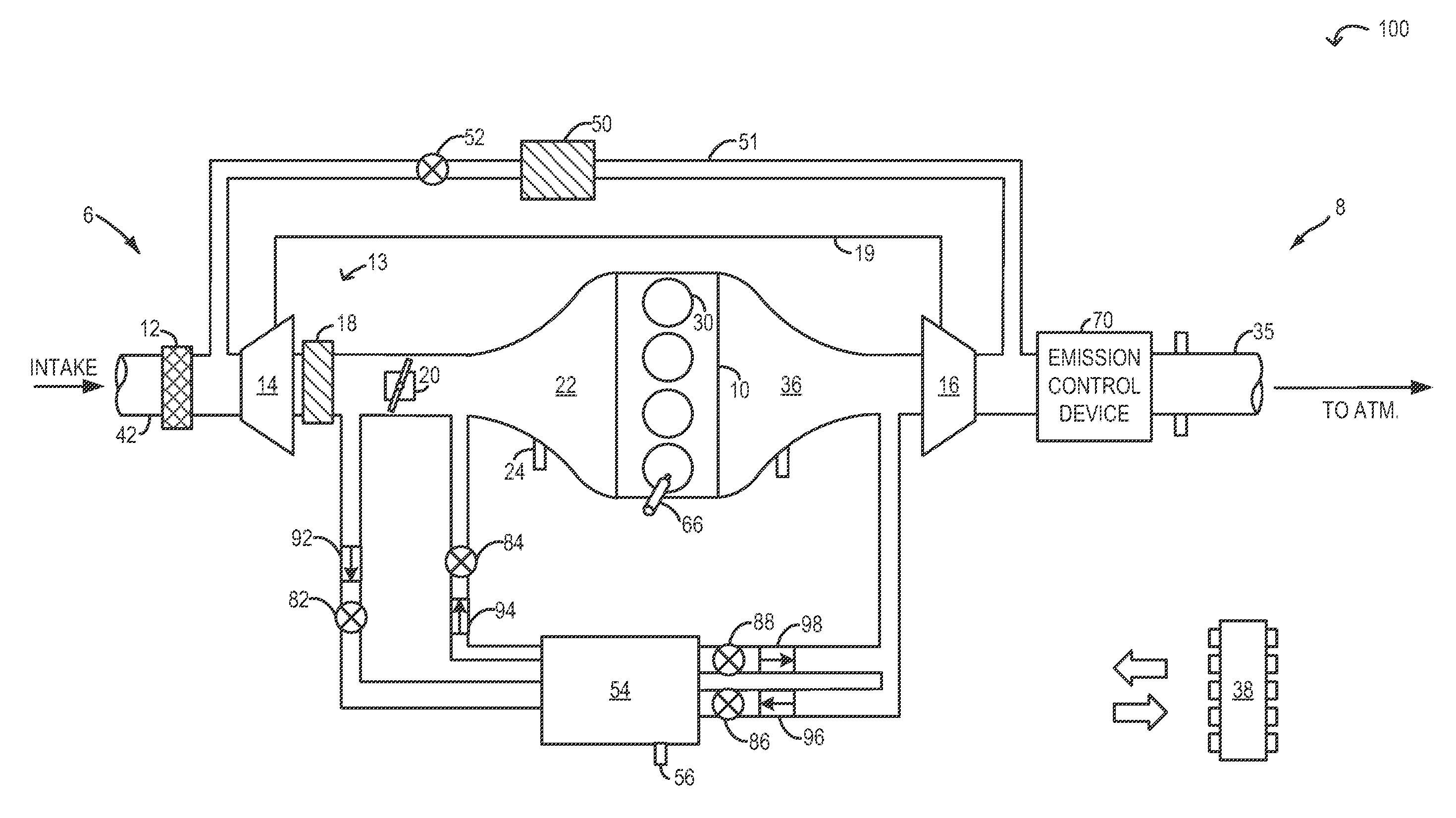
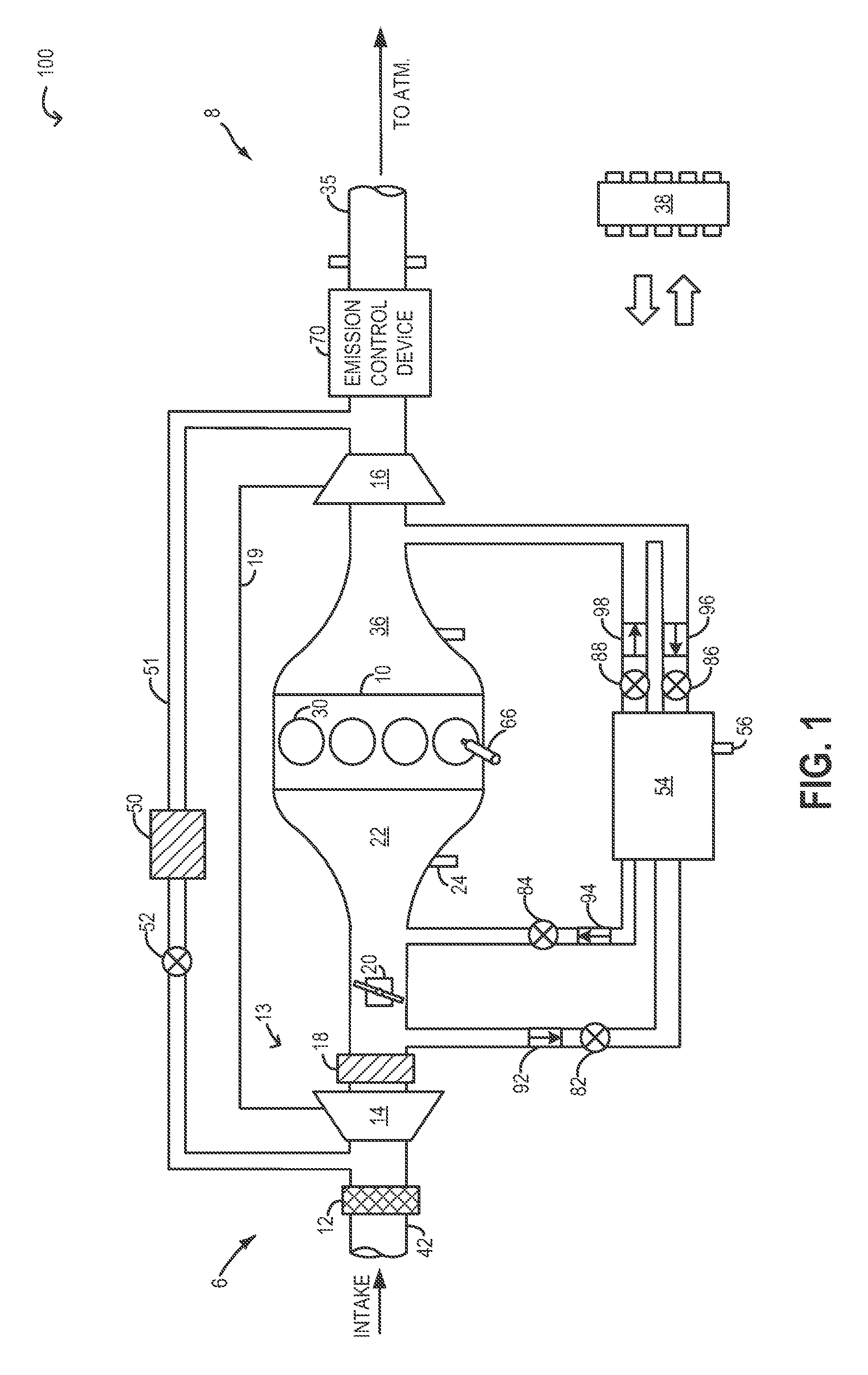
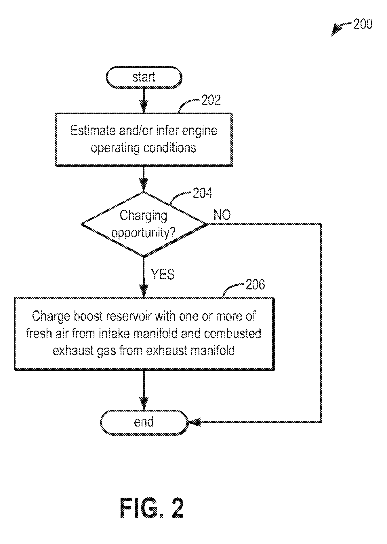
[0014]The following description relates to systems and methods for reducing turbo lag in a boosted engine including a boost air reservoir, such as in the engine system of FIG. 1. By discharging pressurized charge from the boost reservoir to the intake manifold or exhaust manifold in response to a tip-in, exhaust gas temperatures and pressures can be quickly raised, and a boosting device turbine can be rapidly spun-up. An engine controller may be configured to perform a control routine, such as the example method of FIG. 2, to charge the boost air reservoir with one or more of combusted exhaust gas from the exhaust manifold or fresh intake air from the intake manifold, when charging opportunities are available. The controller may be further configured to perform a control routine, such as the example method of FIG. 3, to discharge the pressurized charge from the reservoir into the intake manifold and / or the exhaust manifold based on engine operating conditions as well as the composit...


PUM


Abstract

Methods and systems are provided for reducing turbo lag in a boosted engine. A boost reservoir coupled to the engine may be charged with compressed intake air and / or combusted exhaust gas. The pressurized charge may then be discharged during a tip-in to either the intake or the exhaust manifold.

Description

TECHNICAL FIELD[0001]This application relates to the field of motor-vehicle engineering, and more particularly, to air induction in motor vehicle engine systems.BACKGROUND AND SUMMARY[0002]A boosted engine may offer greater fuel efficiency and lower emissions than a naturally aspirated engine of similar power. During transient conditions, however, the power, fuel efficiency, and emissions-control performance of a boosted engine may suffer. Such transient conditions may include rapidly increasing or decreasing engine load, engine speed, or mass air flow. For example, when the engine load increases rapidly, a turbocharger compressor may require increased torque to deliver an increased air flow. Such torque may not be available, however, if the turbine that drives the compressor is not fully spun up. As a result, an undesirable power lag may occur before the intake air flow builds to the required level.[0003]It has been recognized previously that a turbocharged engine system may be ada...

Claims


Application Information

Patent Timeline
Patent Type & Authority Patents(United States)
IPC IPC(8): F02B33/44F01N3/00F02D41/10F02D41/00F02D23/02F02B37/14
CPCF02M26/05F02B37/14F02D23/02F02D41/0007F02D41/10F02M26/37F02M26/34F02M26/04Y02T10/144F02M26/09Y02T10/12
Inventor ROLLINGER, JOHN ERICRICHARDS, ADAM J.BELL, DAVIDWADE, ROBERT ANDREW
Owner FORD GLOBAL TECH LLC
Why Eureka
Try Eureka