Internal combustion engine

Active Publication Date: 2018-10-11
TOYOTA JIDOSHA KK
View PDF6 Cites 4 Cited by
  • Summary
  • Abstract
  • Description
  • Claims
  • Application Information

AI Technical Summary

Benefits of technology

The disclosure describes an internal combustion engine that can improve fuel efficiency and reduce turbo lag. This means that the engine can use less fuel and respond faster to energy demands, which can improve its overall performance.

Problems solved by technology

However, in a case where the needed load of the internal combustion engine is sharply increased due to acceleration or the like of a vehicle provided with the internal combustion engine, the turbocharging performed by the turbocharger takes substantial time.
Therefore, intake air amount cannot be rapidly increased to a target value.
However, when late closing or early closing of the intake valve is performed in the internal combustion engine of the Atkinson cycle, the intake air amount is small.
Therefore, knocking is likely to occur.
However, when the ignition timing is retarded, thermal efficiency decreases and the output of the internal combustion engine decreases.

Method used


Image

  • Internal combustion engine
  • Internal combustion engine
  • Internal combustion engine

Examples


first embodiment

[0037]First, a first embodiment will be described with reference to FIGS. 1 to 13.

[0038]Configuration of Internal Combustion Engine

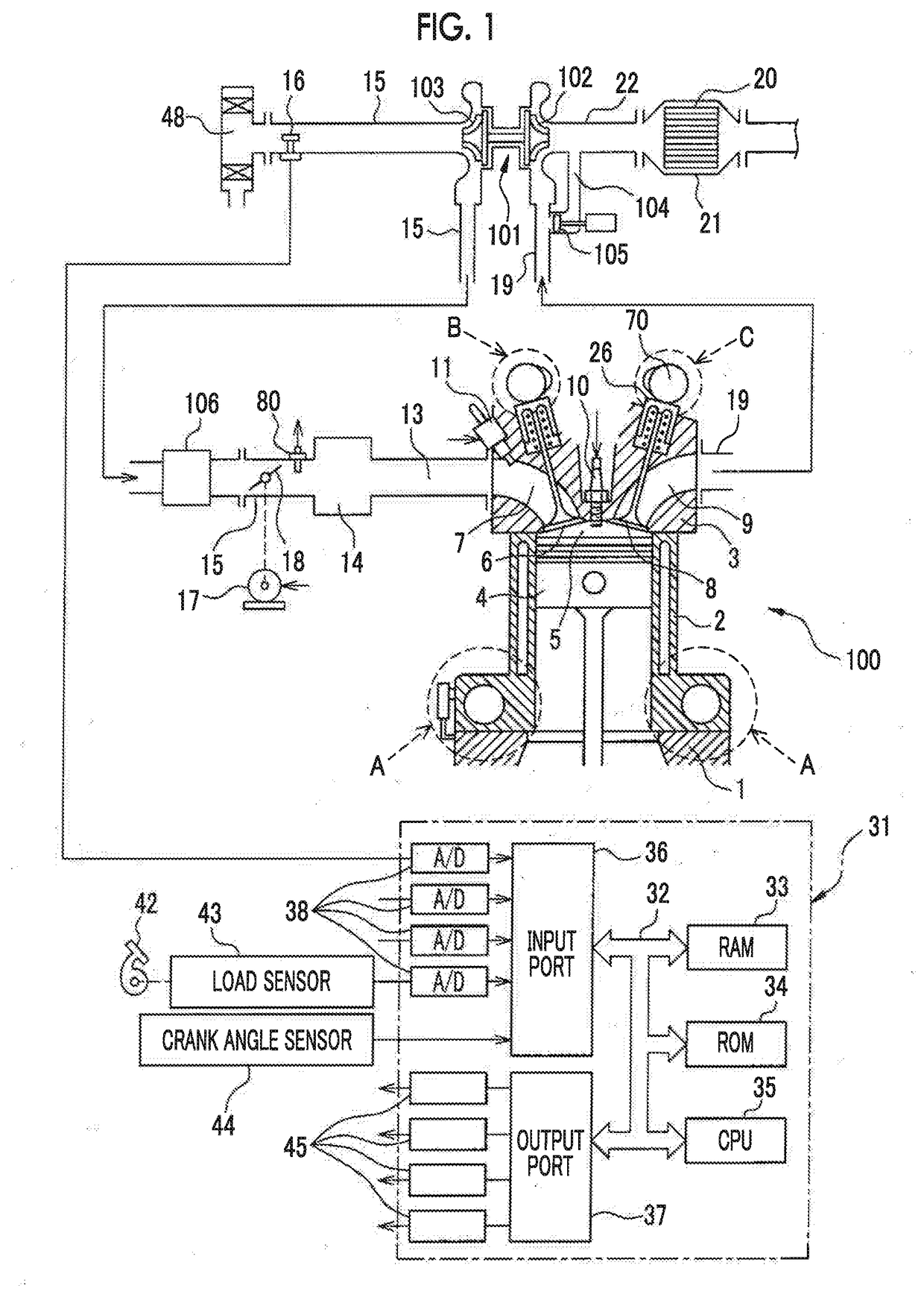
[0039]FIG. 1 is a view schematically illustrating an internal combustion engine 100 related to a first embodiment. In the first embodiment, the internal combustion engine 100 is a spark-ignition type internal combustion engine (gasoline engine). The internal combustion engine 100 is mounted on a vehicle. The internal combustion engine 100 includes a crankcase 1, a cylinder block 2, and a cylinder head 3. A piston 4 that reciprocates inside the cylinder block 2 is disposed inside the cylinder block 2. The internal combustion engine 100 has a plurality of cylinders. In the first embodiment, the number of cylinders is four.

[0040]A combustion chamber 5 is formed between the piston 4 and the cylinder head 3 for each cylinder. An intake port 7 and an exhaust port 9 are formed in the cylinder head 3. The intake port 7 and the exhaust port 9 are connected to the...

second embodiment

[0113]The configuration and control of an internal combustion engine related to a second embodiment are basically the same as those of the internal combustion engine related to the first embodiment except for the points to be described below. For this reason, the second embodiment will be described below, mainly regarding the parts different from the first embodiment.

[0114]In the second embodiment, similar to the first embodiment, the electronic control unit of the internal combustion engine 100 calculates the steady valve closing timing IVCs and the transient valve closing timing IVCt, and calculates the target valve closing timing based on the steady valve closing timing IVCs and the transient valve closing timing IVCt. Unlike the first embodiment, the electronic control unit calculates the target mechanical compression ratio based on the target valve closing timing.

[0115]FIG. 14 is a flowchart illustrating the control in the second embodiment. A control routine of FIG. 14 is repe...

third embodiment

[0120]The configuration and control of an internal combustion engine related to a third embodiment are basically the same as those of the internal combustion engine related to the first embodiment except for the points to be described below. For this reason, the third embodiment will be described below mainly regarding the parts different from the first embodiment.

[0121]In the third embodiment, the electronic control unit of the internal combustion engine 100 sets the target valve closing timing TIVC to the transient valve closing timing IVCt when a difference between the transient valve closing timing IVCt and the steady valve closing timing IVCs becomes equal to or more than a first reference value, and switches the target valve closing timing TIVC from the transient valve closing timing IVCt to the steady valve closing timing IVCs when the difference between the transient valve closing timing IVCt and the steady valve closing timing IVCs becomes equal to or less than a second ref...


PUM


Abstract

An internal combustion engine includes a turbocharger, a variable valve timing mechanism, a variable compression ratio mechanism, and an electronic control unit that controls the variable compression ratio mechanism such that the mechanical compression ratio becomes a target mechanical compression ratio and controls the variable valve timing mechanism such that the valve closing timing of the intake valve becomes a target valve closing timing. The electronic control unit brings the target valve closing timing close to an intake bottom dead center and make the target mechanical compression ratio low, compared to a steady state after the intake pressure reaches a target pressure, in a transient state before the intake pressure reaches the target pressure in a case where the intake pressure is increased to the target pressure higher than an atmospheric pressure by the turbocharger.

Description

INCORPORATION BY REFERENCE[0001]The disclosure of Japanese Patent Application No. 2017-078375 filed on Apr. 11, 2017 including the specification, drawings and abstract is incorporated herein by reference in its entirety.BACKGROUND1. Technical Field[0002]The present disclosure relates to an internal combustion engine.2. Description of Related Art[0003]In the related art, it is known that a turbocharger is provided at an internal combustion engine of the Atkinson cycle in which an expansion ratio is made higher than a compression ratio due to late closing or early closing of an intake valve (for example, Japanese Unexamined Patent Application Publication No. 2005-090425 (JP 2005-090425 A)). The turbocharger is driven by exhaust gas to increase intake pressure. The turbocharging performed by the turbocharger increases the intake air amount and increases the output of the internal combustion engine.[0004]However, in a case where the needed load of the internal combustion engine is sharp...

Claims


Application Information

Patent Timeline
IPC IPC(8): F01L13/08F02D15/02F02D13/02F02B75/04F02D41/10
CPCF01L13/08F02D15/02F02D13/0215F02B75/045F02D41/10F02D2700/03F16C7/06F02D23/00F02D2200/602F02D2250/34F02D13/0234F02D15/00F02D37/00F02D41/0007F02D2041/001F02D2200/0406F02D2200/101F02D13/0269F02D15/04Y02T10/12F02B37/00F02B75/04F02D13/02
Inventor NAKASAKA, YUKIHIRO
Owner TOYOTA JIDOSHA KK
Why Eureka
Try Eureka