Coordination of secondary air and blow-through air delivery

a secondary air and air delivery technology, applied in the direction of electric control, ignition automatic control, machines/engines, etc., can solve the problems of undesirable power lag, torque may not be available, power, fuel efficiency, emissions-control performance of a boosted engine, etc., to achieve greater fuel efficiency, lower emissions, and power. the effect of reducing emissions

Active Publication Date: 2016-10-18
FORD GLOBAL TECH LLC
View PDF16 Cites 3 Cited by
  • Summary
  • Abstract
  • Description
  • Claims
  • Application Information

AI Technical Summary

Benefits of technology

[0003]It has been recognized previously that a turbocharged engine system may be adapted to provide “blow-through” air wherein boosted intake air is driven from the intake manifold, downstream of the compressor, through the engine cylinder(s) and into the exhaust manifold, upstream of the turbine. For example, a variable cam timing (VCT) system may be temporarily adjusted to provide high valve overlap. During the positive valve overlap, the boosted air is inducted through the cylinders into the turbine to temporarily provide extra mass flow and enthalpy in the exhaust. The extra turbine energy enables the turbine to spin-up faster, thereby reducing turbo lag.
[0005]Thus, at least some of the above issues may be addressed by a method for a turbocharged engine comprising: supplying compressed air through a throttle to an engine from a compressor driven by a turbine coupled to an exhaust of the engine; and during tip-in of the throttle, reducing turbo-lag by delivering ambient air to the turbine during a first mode of operation and during a second mode of operation providing blow-through of a portion of the compressed air through the engine, without combustion, to the turbine.
[0006]As an example, in response to a tip-in, a secondary air pump may be utilized to deliver secondary air in to an exhaust manifold upstream of a turbine. At the same time, enrichment may be provided to generate high levels of engine out carbon monoxide (CO), hydrogen (H2), and hydrocarbons to react with the secondary air in the exhaust. As a result, mass and enthalpy of the exhaust may be increased, which may be utilized to increase a speed of the turbine to a desired speed. Further, due to increase in turbine speed, a boost pressure may be increased. Upon attaining a threshold boost pressure at which sufficient boost may be available for blow-through, engine operation may switch to providing blow-through. That is, secondary air injection may be stopped and blow-through may be utilized to provide extra air in the exhaust.
[0008]By providing secondary air injection early during the tip-in, sufficient boost may be generated, which may be utilized for blow-through. As a result, turbocharger performance may be improved. Further, utilizing secondary air injection during the initial part of the tip-in may allow higher trapped mass in the cylinder (since the extra air in the exhaust required for extra exhaust energy is provided by the secondary air pump instead of the turbocharger). As a result, initial torque output may be improved. Additionally, by utilizing secondary air injection during the early part of tip-in, valve timings may be adjusted to increase initial torque output. Still further, by switching engine operation to additionally or alternatively provide blow-through after sufficient boost is attained, the time required for the turbine to reach a desired speed may be reduced, thereby reducing turbo lag. In this way, secondary air injection and blow-through may be coordinated during tip-in to expedite turbine spin-up and improve initial torque output.

Problems solved by technology

During transient conditions, however, the power, fuel efficiency, and emissions-control performance of a boosted engine may suffer.
Such torque may not be available if the turbine that drives the compressor is not fully spun up.
As a result, an undesirable power lag may occur before the intake air flow builds to the required level.
However, the inventors herein have identified potential issues with such an approach.
However, operating the engine with high levels of spark retard may cause combustion to occur later than an optimal timing required for immediate torque output.

Method used


Image

  • Coordination of secondary air and blow-through air delivery
  • Coordination of secondary air and blow-through air delivery
  • Coordination of secondary air and blow-through air delivery

Examples


Embodiment Construction

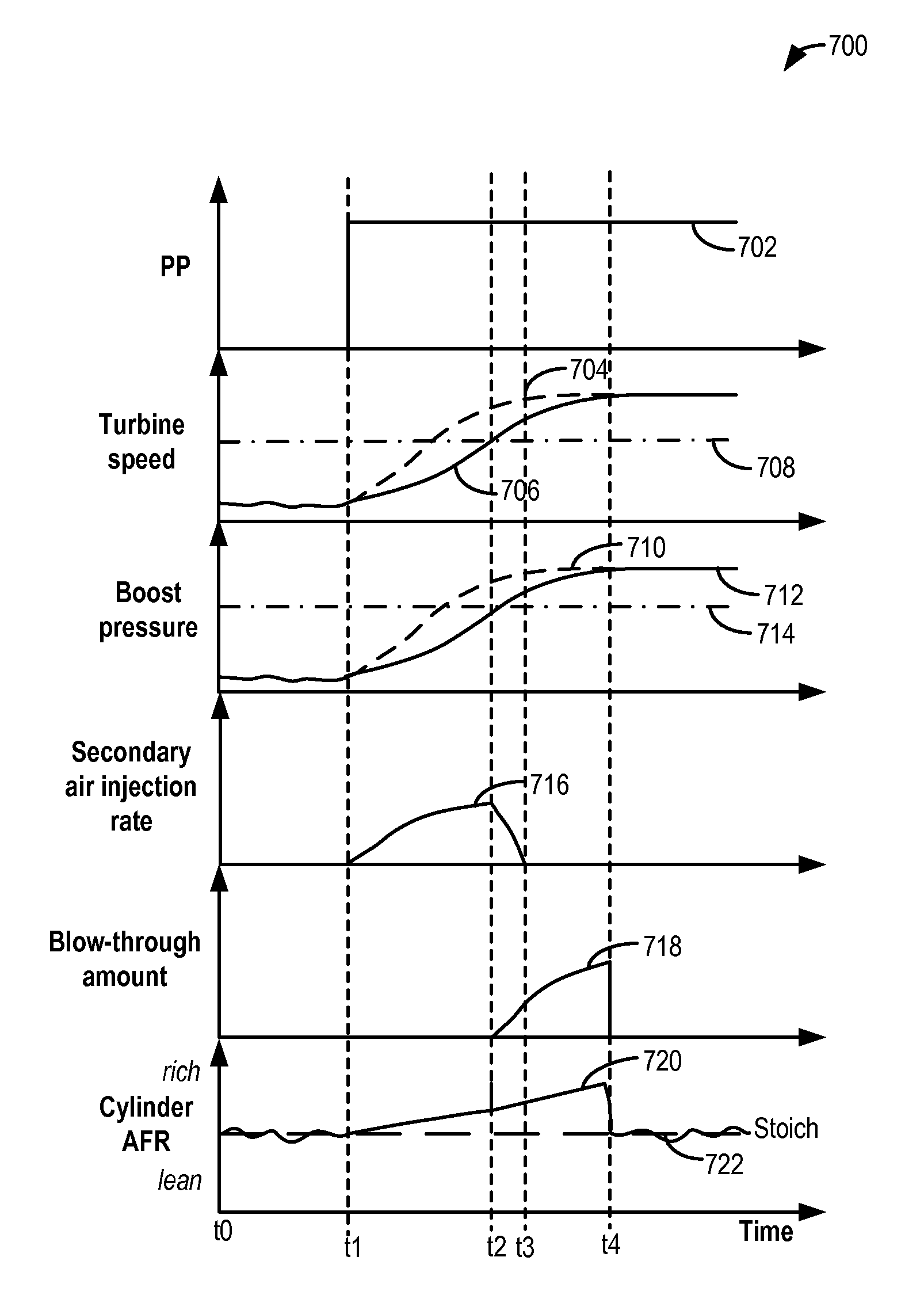
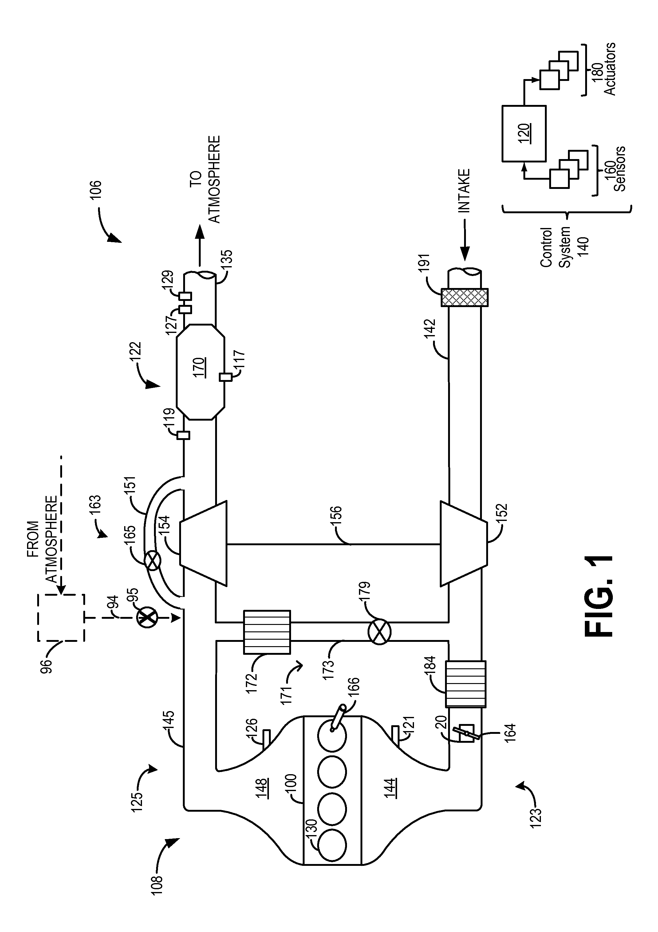
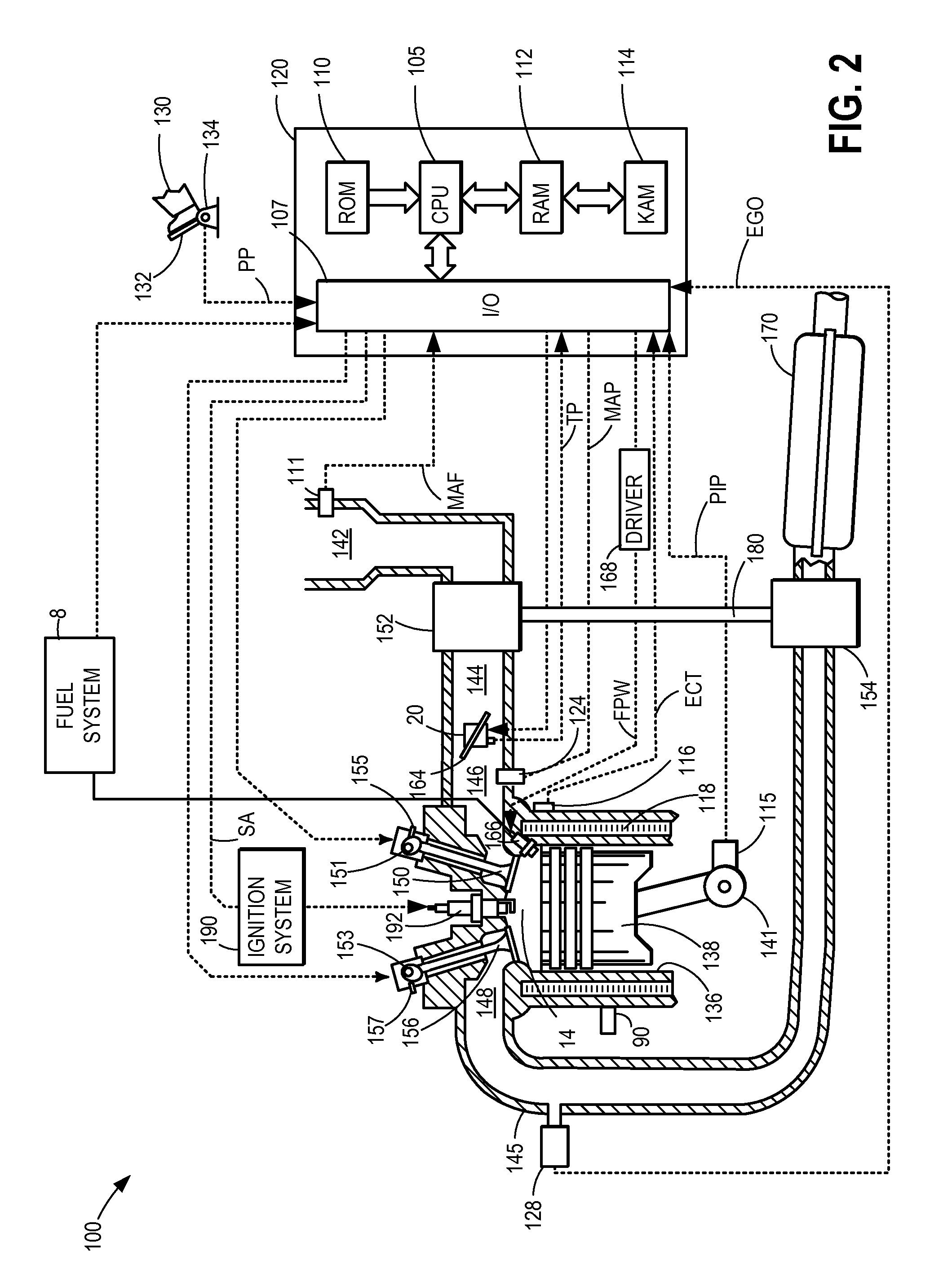
[0017]Methods and systems are provided for reducing turbo lag in a vehicle engine, such as the engine system depicted at FIGS. 1-2. During a tip-in, secondary air injection and blow-through may be coordinated to expedite spinning of a turbine to a desired speed, and increase initial torque output. A controller may be configured to perform control routines, such as the example routines of FIGS. 3-6 to determine a type of engine operation that may be performed (e.g., secondary air injection and / or blow-through) during the tip-in, and to adjust the engine operation based on the type of operating mode. Example secondary air injection and blow-through adjustments are described at FIG. 7.

[0018]FIG. 1 shows a schematic depiction of a vehicle system 106. The vehicle system 106 includes an engine system 108, including engine 100 coupled to emission control system 122. Engine 100 includes a plurality of cylinders 14. Engine 100 also includes an intake 123 and an exhaust 125. Intake 123 may re...


PUM


Abstract

Methods and systems are provided for controlling and coordinating secondary air injection and blow-through to reduce turbo lag. By utilizing secondary air injection prior to providing blow-through, and deactivating the secondary air pump when a desired boost pressure for blow-through is achieved, turbine spin-up to a desired speed may be expedited and initial torque output may be increased.

Description

TECHNICAL FIELD[0001]The present description relates generally to methods and systems for improving turbo lag and torque output with coordination of secondary air injection and blow-through air in a boosted internal combustion engine.BACKGROUND AND SUMMARY[0002]A boosted engine may offer greater fuel efficiency and lower emissions than a naturally aspirated engine of similar power. During transient conditions, however, the power, fuel efficiency, and emissions-control performance of a boosted engine may suffer. Such transient conditions may include rapidly increasing or decreasing engine load, engine speed, or mass air flow. For example, when the engine load increases rapidly, a turbocharger compressor may require increased torque to deliver an increased air flow. Such torque may not be available if the turbine that drives the compressor is not fully spun up. As a result, an undesirable power lag may occur before the intake air flow builds to the required level.[0003]It has been rec...

Claims


Application Information

Patent Timeline
Patent Type & Authority Patents(United States)
IPC IPC(8): F02D13/02F01L1/34F02D41/10F02D41/14F02D41/18F02P5/04F02P5/15F02D37/02F02B33/04F02D23/02F02D41/00F02B37/12F02B37/18
CPCF02M26/04F01L1/34F02B37/12F02D13/0215F02D13/0261F02D23/02F02D41/10F02D41/1448F02D41/182F02M26/05F02P5/045F02P5/1504F02D37/02F02D41/0007F02B37/18F02B2037/122F02D2041/001F02D2200/0406F02D2200/602F02D2250/18F02D2250/22Y02T10/121F02M26/17Y02T10/12Y02T10/40
Inventor LEONE, THOMAS G.
Owner FORD GLOBAL TECH LLC
Why Eureka
Try Eureka