Method and apparatus for injecting hydrogen within an engine

Active Publication Date: 2013-09-26
FORD GLOBAL TECH LLC
View PDF3 Cites 0 Cited by
  • Summary
  • Abstract
  • Description
  • Claims
  • Application Information

AI Technical Summary

Benefits of technology

The invention is about improving engine performance by injecting hydrogen into the engine to increase the speed of the turbocharger. By delivering hydrogen to the exhaust system and allowing it to combust and expand, turbine speed may increase and turbo lag (the delay in achieving boosted aircharge to the engine) may decrease. This solution is cost-effective and easy to control.

Problems solved by technology

However, the accumulation of the increased amount of work requires time, thus more time elapses between turbo boost and throttle actuation, increasing turbo lag.
However, these solutions are bulky, costly and challenging to control.
This, however, does not provide a means of reducing turbo lag.

Method used


Image

  • Method and apparatus for injecting hydrogen within an engine
  • Method and apparatus for injecting hydrogen within an engine
  • Method and apparatus for injecting hydrogen within an engine

Examples


Embodiment Construction

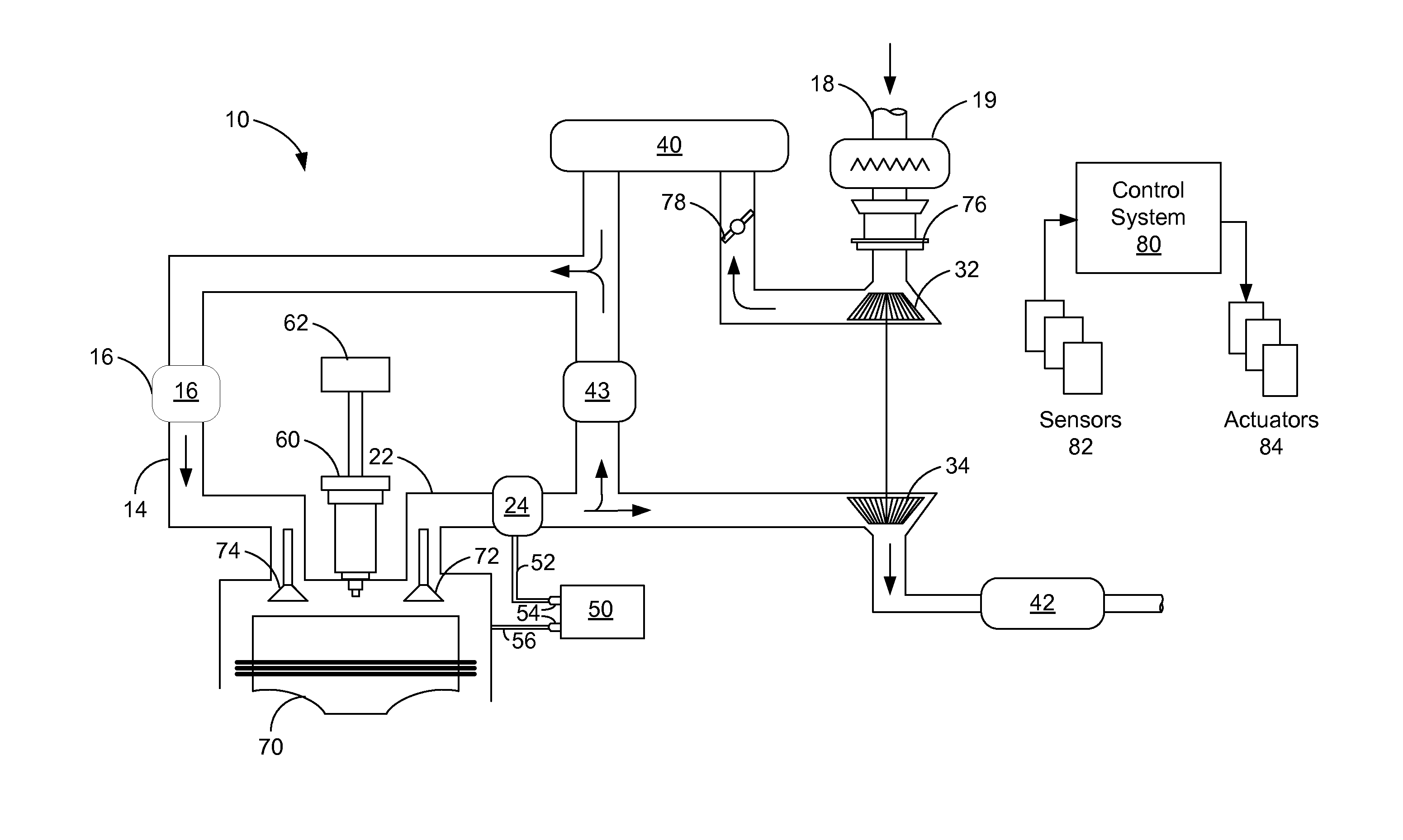
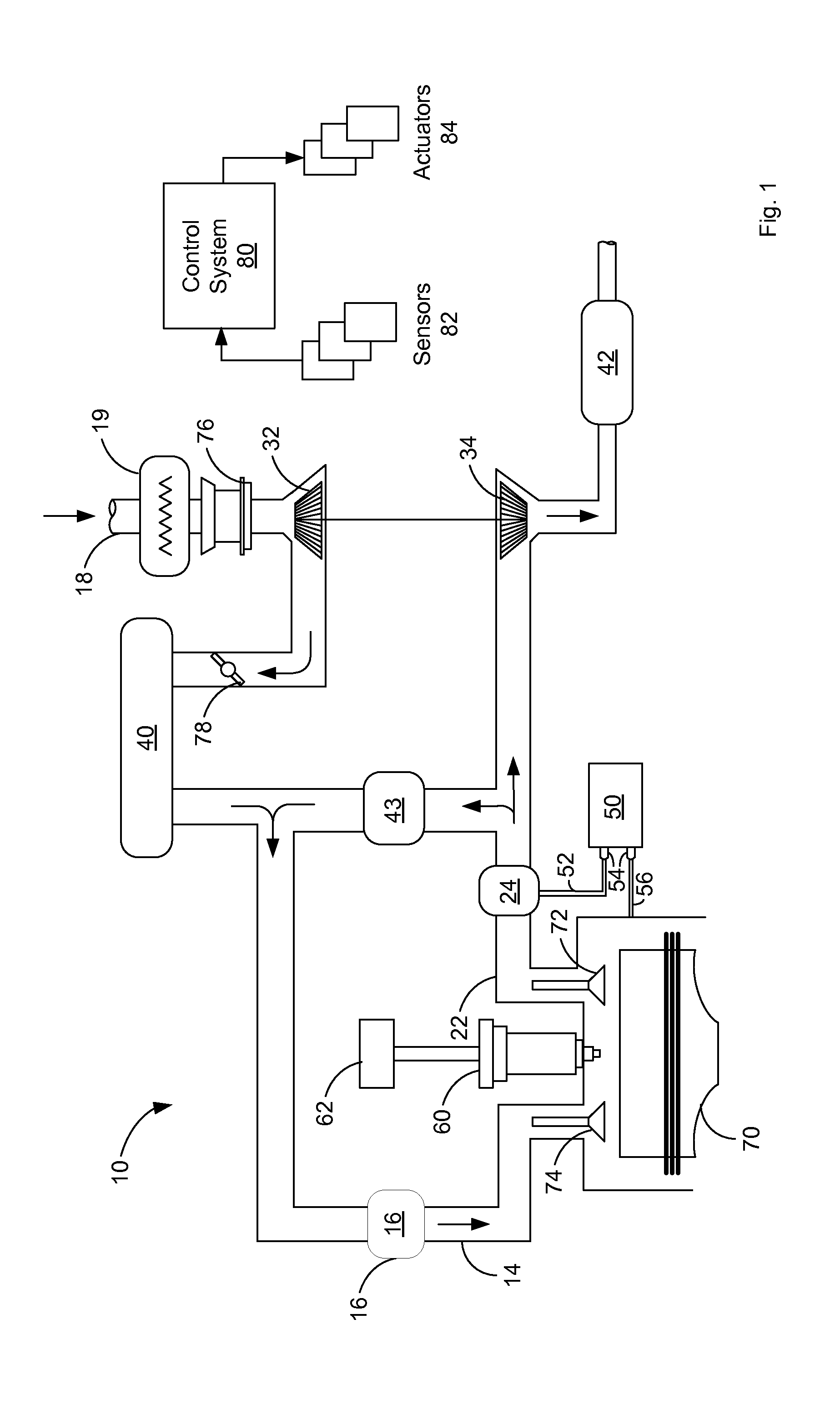
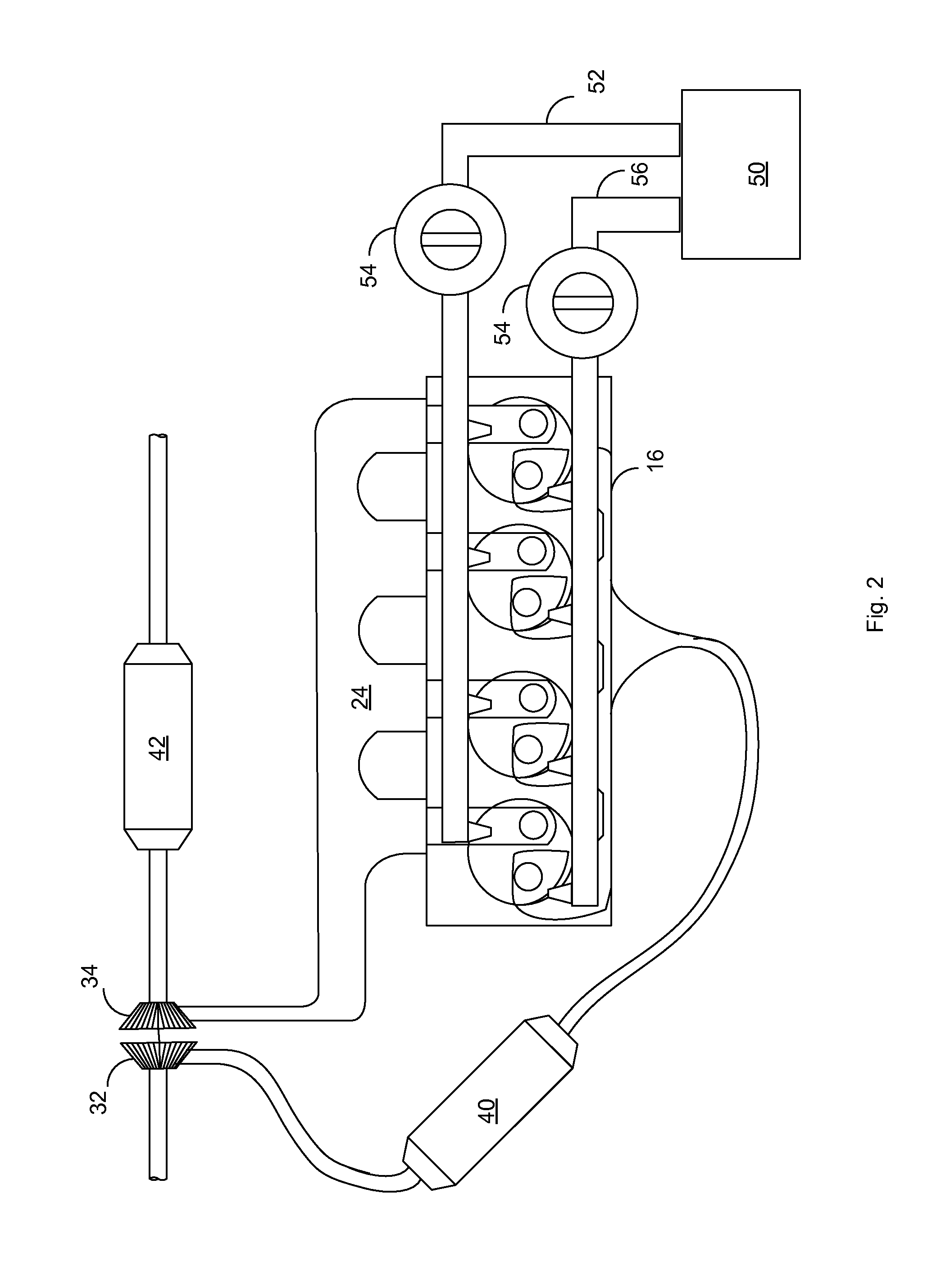
[0015]FIG. 1 schematically depicts an example embodiment of an engine system that includes EGR and a hydrogen recirculation device. FIG. 2 shows an example embodiment of a 4 cylinder in-line engine system including a hydrogen delivery apparatus. FIG. 3 diagrams an example operating method of engine operation. FIG. 4 diagrams an alternate example method of engine operation.

[0016]FIG. 1 shows one cylinder 12 of a multi-cylinder engine system 10 that may be included in the propulsion system of a vehicle. Though not shown, cylinder 12 may be part of an inline, V-shaped, or any configuration engine of any number of cylinders. Ambient air may enter the engine system via an air inlet 18. Low pressure throttle 76 may be actuated by control system 80 via actuators 84. Throttle 76 may be controlled by control system 80 via an input device actuated by a vehicle operator. The input device may include an accelerator pedal 86 and an accelerator pedal position sensor 88 that generates a proportion...


PUM


Abstract

An engine system comprising: an exhaust gas system for removing exhaust gas from the engine; a turbocharger comprising a compressor for inducing air towards the engine and a turbine provided along the exhaust gas system and driven by removed exhaust gas for powering the compressor; a hydrogen delivery apparatus adapted to deliver hydrogen to the exhaust gas system such that the hydrogen can combust and expand, thereby increasing the speed of the turbine. The increased speed of the turbine operation decreases turbo lag and increases engine responsiveness.

Description

CROSS REFERENCE TO RELATED APPLICATIONS[0001]The present application claims priority to United Kingdom Patent Application No. 1205221.3, filed on Mar. 26, 2012, the entire contents of which are hereby incorporated by reference for all purposes.BACKGROUND AND SUMMARY[0002]The present invention relates to a method and apparatus for injecting hydrogen within an engine. In particular, the invention relates to injecting hydrogen within an engine of a vehicle to increase the speed of a turbocharger.[0003]In a turbocharged engine, a turbocharger may include a compressor to compress air intake from the atmosphere or an exhaust gas recirculation (EGR) system, to be delivered to the engine for combustion. By increasing the mass of air entering the engine, the expansive power of combusted energy is increased resulting in increased available torque and thus power and efficiency.[0004]A compressor may be coupled to a high speed turbine within the exhaust system. A turbine may convert the kinetic...

Claims


Application Information

Patent Timeline
IPC IPC(8): F02B37/10
CPCF02B37/10F02B37/20Y02T10/144Y02T10/12
Inventor CAINE, JONATHAN EDWARD
Owner FORD GLOBAL TECH LLC
Why Eureka
Try Eureka