Surface mounting lamp

a technology for mounting lamps and surface lamps, which is applied in the direction of vessel illumination signalling, lighting and heating apparatus, lighting applications, etc., can solve the problems of high installation costs, significant impact on the structural continuity of the support, and high installation costs, and achieves the effect of convenient assembly

Active Publication Date: 2016-03-08
CALZONI
View PDF6 Cites 3 Cited by
  • Summary
  • Abstract
  • Description
  • Claims
  • Application Information

AI Technical Summary

Benefits of technology

[0013]More specifically, it is an aim of this invention to provide a surface mounting lamp that is particularly slim and at the same time robust.
[0014]Another aim of the invention is to provide a surface mounting lamp that can provide side lighting along the surface the lamp is mounted on.
[0015]Yet another aim of the invention is to provide a surface mounting lamp that is easy to make and quick to install.
[0019]Preferably, the retaining means are of a chemical type, that is, defined by a layer of adhesive material (for example, epoxy glue) or sealing material so as not to subject the structure of the covering element to mechanical stress.

Problems solved by technology

Thus, prior art surface mounting lamps, especially when they require large emitting surfaces for purposes of visibility as mentioned above (for example, an illuminated line) involve making large openings in the mounting surface which in turn means not only high installation costs but also a significant impact on the structural continuity of the support.
Disadvantageously, that means the covers have to be particularly thick because they have to resist the high stress transmitted to them by the flange.

Method used


Image

  • Surface mounting lamp
  • Surface mounting lamp
  • Surface mounting lamp

Examples


first embodiment

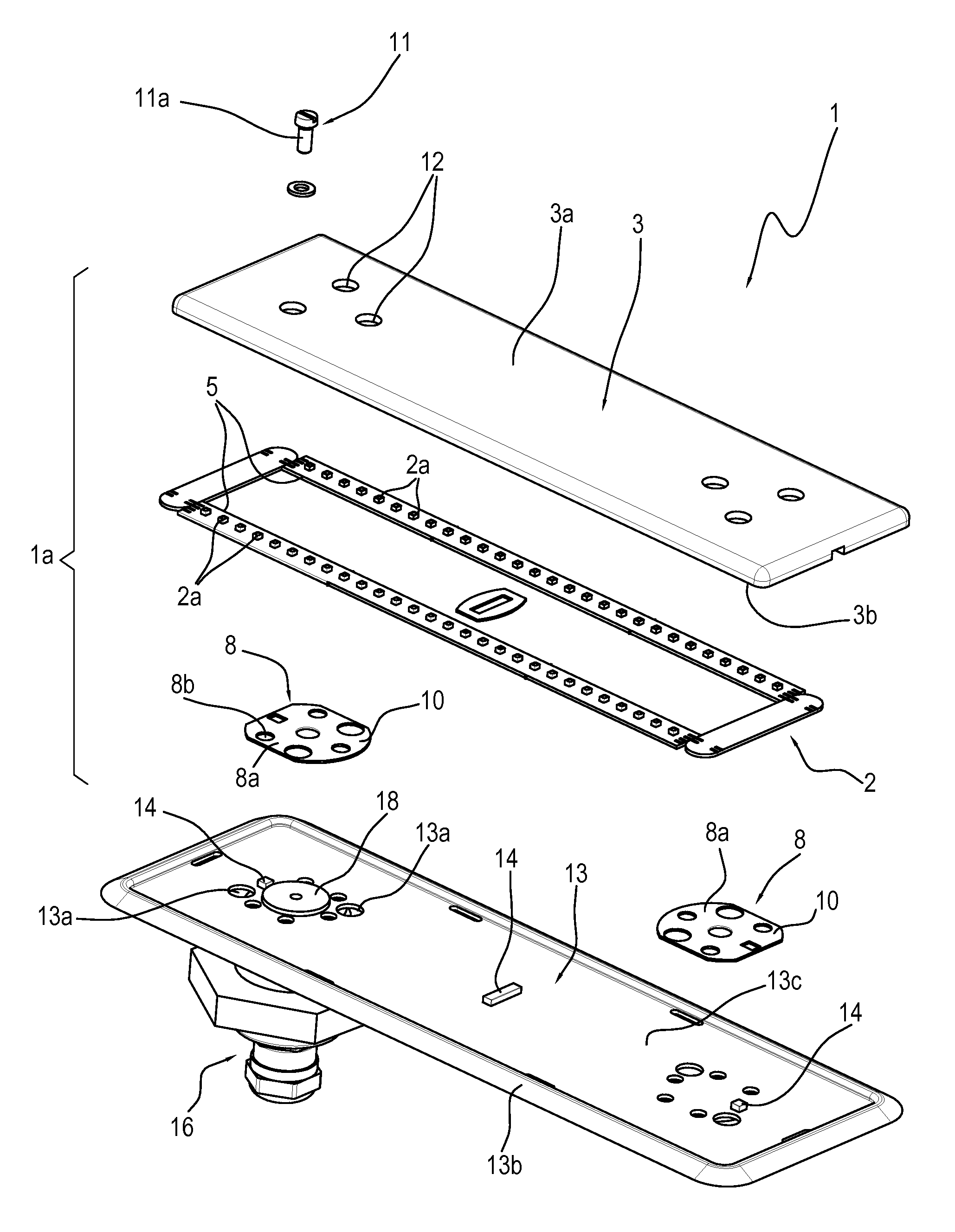
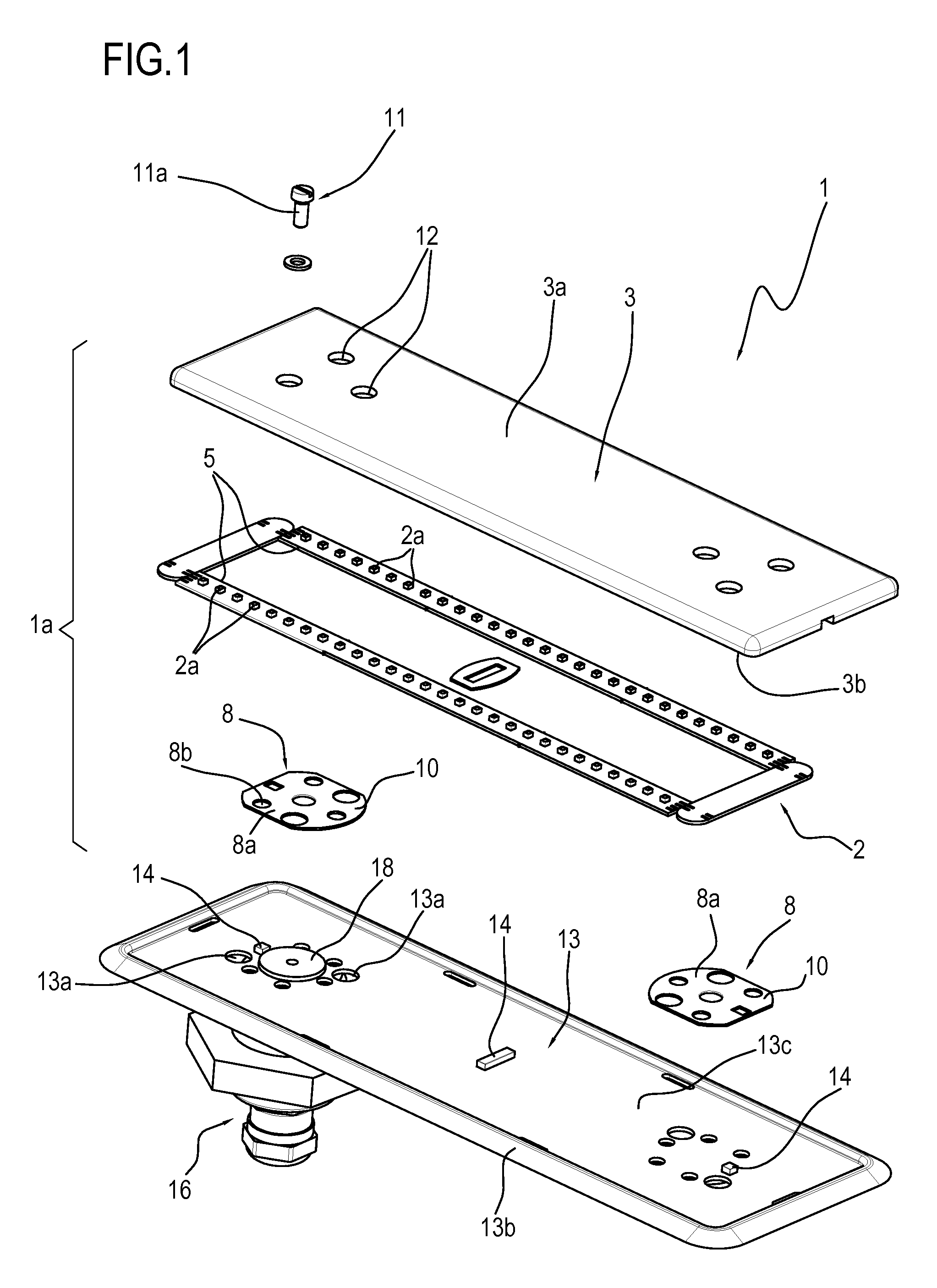
[0054]In a first embodiment, the covering element 3 is provided with one or more sockets 4, each adapted to house two or more lighting elements 2a.

[0055]Thus, the covering element 3 is a substantially full element made in such a way as to define a plurality of sockets 4 or grooves in which the lighting elements 2a of the lighting unit 2 are housed.

[0056]Advantageously, that way, the thickness of the lamp 1 is limited because the lighting elements 2a do not add their thickness to that of the covering element 3 but are embedded in the latter and housed in the sockets 4.

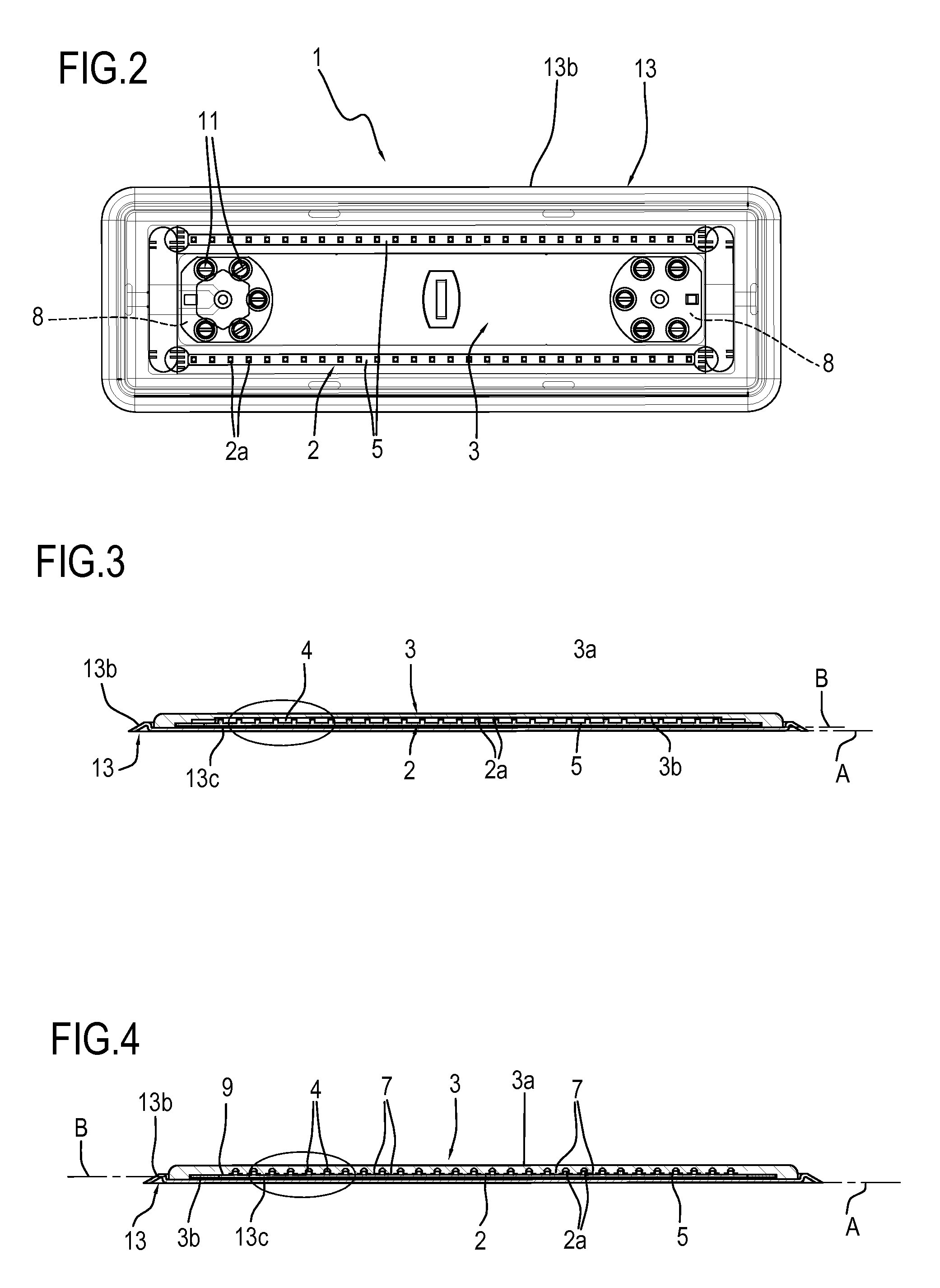
[0057]With reference to FIGS. 3 and 3a, the covering element 3 presents a pair of sockets 4, or grooves of a size such as to accommodate all the lighting elements 2a under a single vault.

[0058]In this embodiment, the lighting unit 2 comprises two printed circuits which are electrically connected to each other to define a single body and each housed in a respective socket 4.

second embodiment

[0059]In a second embodiment, each socket 4 is adapted to house a single lighting element 2a.

[0060]With reference to FIGS. 4 and 4a, the covering element 3 presents a plurality of sockets 4 each being of a size such as to accommodate a single lighting element.

[0061]Thus, the covering element 3 is provided with a series of sockets arranged to mirror the lighting elements.

[0062]In the embodiment illustrated, each socket is larger in volume than the respective lighting element 2a.

[0063]Thus, there is an air volume between the lighting element 2a and the intrados of the socket 4.

[0064]Alternatively, however, each socket 4 might be exactly shaped to match the respective lighting element 2a.

[0065]In this embodiment, therefore, each lighting element 2a is recessed in the respective socket 4 and remains in contact with the intrados thereof.

[0066]Thus, the covering element 3 and the lighting unit 2 substantially define a single block, without empty spaces.

[0067]This configuration is obtai...


PUM


Abstract

A surface mounting lamp includes a covering element of a transparent material and having a first face, which in use is directed outwards away from a mounting surface of the lamp, and a second face opposite the first face and provided with at least one socket for housing lighting elements. A lighting unit is sealably connected to the covering element, facing the inside of the socket and includes a plurality of lighting elements, each housed in the socket. The lamp also includes a junction piece connected to the covering element and having a connecting portion engageable with the mounting surface of the lamp to fix the position thereof, and a retaining mechanism interposed between the junction piece and the second face of the covering element and connecting the covering element to the junction piece.

Description

[0001]This application claims priority to Italian Patent Application B02012A000572 filed Oct. 19, 2012, the entirety of which is incorporated by reference herein.BACKGROUND OF THE INVENTION[0002]This invention relates to a surface mounting lamp, that is, a lamp configured to be installed flush with a supporting surface.[0003]The invention is applicable in particular in the field of aviation, particularly for lighting landing decks or helipads on both land and offshore platforms and on board ships.[0004]In effect, these lamps are installed on a flat surface in such a way as to protrude just a little from the surface in order to provide a delimited illuminated indication along the surface which may be defined either by covered ground (tarmac or paving) or by slabs and metal frames (on board ships).[0005]Current solutions for installation on the ground and even on landing decks involve making an opening in the lamp mounting (or installation) surface, where the lamp can be recessed and ...

Claims


Application Information

Patent Timeline
Patent Type & Authority Patents(United States)
IPC IPC(8): F21S4/00F21V17/10F21S8/00F21V3/00F21V31/00B63B45/06F21V21/00F21V17/12B64F1/20F21W111/06F21Y103/00F21Y105/00
CPCF21V31/005B63B45/06F21S8/032F21V3/00F21V17/101B64F1/20F21V17/12F21W2111/06F21Y2101/02F21Y2103/003F21Y2105/001F21Y2105/10F21Y2103/10F21Y2115/10
Inventor BERTIN, DANIELE, MARIA
Owner CALZONI
Why Eureka
Try Eureka