Aircraft docking system

a technology for aircraft and docking systems, applied in traffic control systems, surveying and navigation, instruments, etc., can solve problems such as disturbance of airport operation, inability to dock, and inability to give guidance to the docking system, so as to improve the ability to determine, reduce the waiting time for aircraft, and improve the effect of airport operation

Active Publication Date: 2016-03-15
SAFEGATE INT
View PDF11 Cites 0 Cited by
  • Summary
  • Abstract
  • Description
  • Claims
  • Application Information

AI Technical Summary

Benefits of technology

[0015]An advantage of the present invention is hence that it provides to an operator of an airport an enhanced ability to determine whether or not it is possible to perform a docking operation when visibility is reduced to such an extent that there exists an uncertainty whether or not safe docking is possible or not. For example, prior art systems are typically unable to distinguish between dense fog or precipitation and parts of approaching aircraft. Needless to say, such lack of distinguishing capability may lead to dangerous situations. On the other hand, prior art systems may be configured to account for such lack of distinguishing ability and simply provide a signal to the effect that docking is impossible when the system is uncertain. This, however, means that the availability of prior art systems is not as high as the availability of a system according to the present invention.
[0016]Furthermore, an advantage is that it is possible to determine in real-time, and continuously, whether or not the density of the fog or the precipitation makes automatic docking impossible or not and keep the traffic controllers informed about it. The need for marshalling can be foreseen and thereby marshallers can be in place when the aircraft arrive and disturbances in terms of docking delays can be avoided. Efficient airport operation is thereby achieved, e.g. in terms of less waiting time for aircraft and faster and hence more efficient allocation of arriving aircraft to gates and terminals where automatic docking is possible.
[0017]Yet an advantage of the invention is that, by providing a solution to the problems as discussed above, an already existing docking system may be adapted to also provide a signal indicative of the visibility conditions at the docking site. Typically, an implementation will only entail re-programming of control software in the system, which means a large saving in cost when comparing with a situation in which a separate visibility system would be needed. There is no need to adapt any hardware of the existing docking system as the wavelength interval in which a docking system operates is also suitable for operation in connection with the determining of visibility conditions.
[0018]Embodiments of the invention include those where the distance determining means are configured to measure receiver signal properties in terms related to scattering of the electromagnetic radiation. For example, the distance determining means may comprise laser ranging means and the distance determining means may then be configured to measure scattering of the laser radiation. Alternatively, the distance determining means may comprise radar ranging means and the distance determining means may then be configured to measure scattering of radar radiation. In further embodiments, backscattered electromagnetic radiation, or more precisely, a power distribution of the backscattered radiation, indicates the scattering.
[0019]Further embodiments include those where the distance determining means comprise signal reception means comprising imaging means configured to provide two-dimensional images of the docking site and where the distance determining means are configured to measure the at least one property of the receiver signal at least in terms related to a contrast difference between at least two areas within an image. These image areas may correspond to predetermined locations, preferably at a same distance from the system, at the docking site.
[0020]In other words, where the docking system utilizes a two-dimensional imaging technique, the measure of visibility conditions is the contrast in an image. Analysing an image signal used for determining the location of the aircraft and determining the deterioration of this signal caused by the fog or precipitation provides a good indication of whether or not the visibility deterioration exceeds the level above which docking is unsafe or even impossible.

Problems solved by technology

A drawback with such systems is that they do not always allow docking in all weather conditions during which the airport is open for traffic.
A result of this is that, during the conditions when automatic docking is impossible due to fog or precipitation, the dockings has to be carried out manually by marshallers.
A problem with such a situation is that the need for manual marshalling may not be apparent until an aircraft is approaching a gate, and it turns out that the fog or precipitation is too dense for the docking system to be able to give guidance.
At a large airport this may happen at several gates at the same time and as it is not planned it may cause disturbances of the airport operation with associated problems such as added cost or decreased safety.
While the system disclosed in the U.S. Pat. No. 6,563,432 detects, identifies and docks aircrafts and also determines whether a detected object is solid or whether fog or precipitation is present, it does not determine whether automatic docking is impossible or not.
The output of the existing visibility meters is, however, typically not very representative of the conditions at the docking systems as these normally are located at gates in close vicinity of terminal buildings, and as the density of fog usually vary very much over an airport.
Moreover, installing such a visibility meter at each gate is not an optimal solution.
Another disadvantage with such a solution is the added cost of providing a plurality of expensive visibility meters.

Method used


Image

  • Aircraft docking system
  • Aircraft docking system
  • Aircraft docking system

Examples


Embodiment Construction

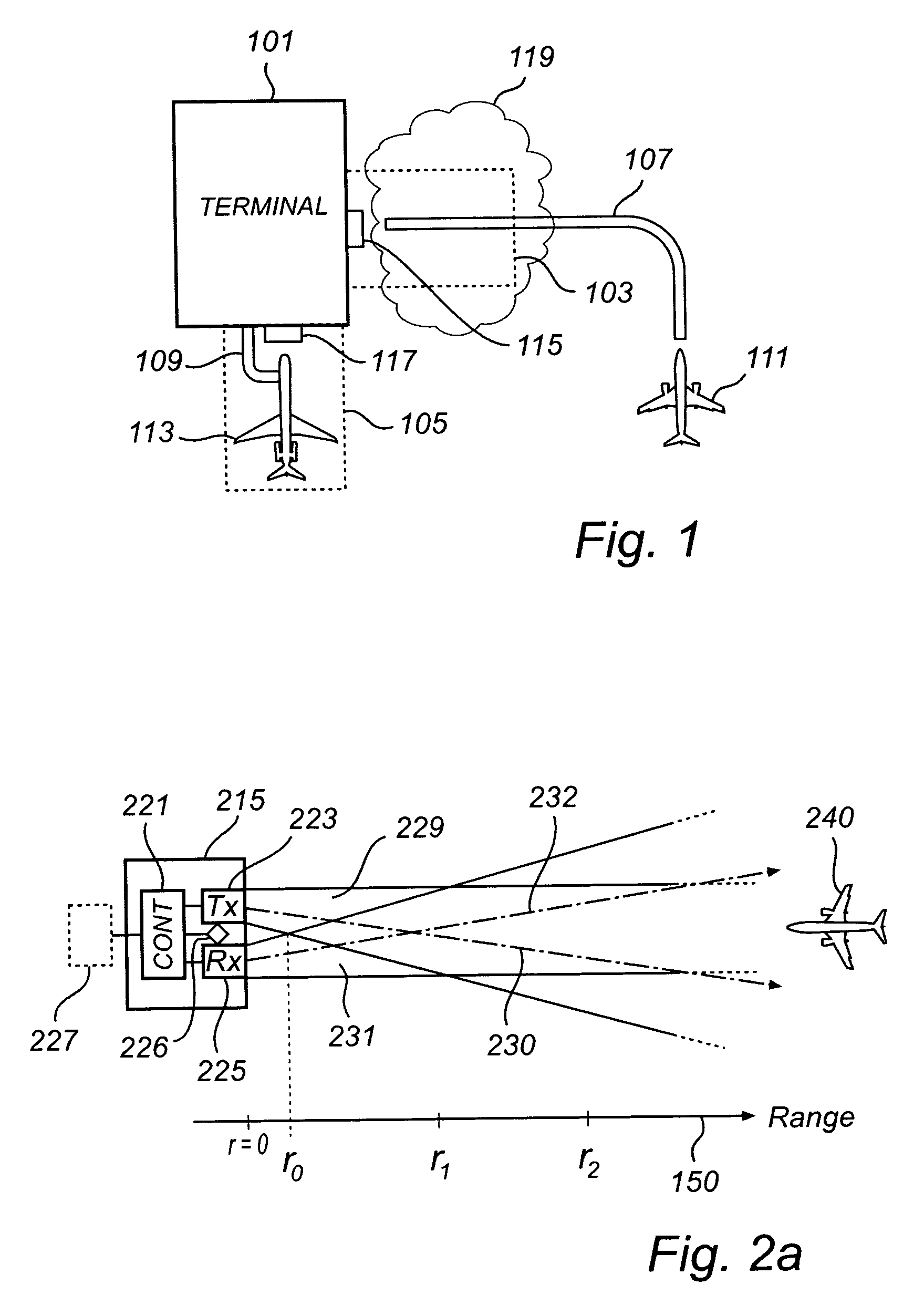
[0028]FIG. 1 illustrates schematically a view from above of a situation at an airport. A terminal 101, which may be a passenger terminal and / or a freight terminal, is configured with a first aircraft docking system 115 and a second aircraft docking system 117. A first docking site 103 and a second docking site 105 are located at each docking system 115, 117 respectively. Although the docking sites are indicated by dashed lines in FIG. 1, these lines need not represent actual markings on the ground but should only be perceived as an aid in reading the present description.

[0029]Moreover, although FIG. 1 shows that both docking systems 115, 117 are attached to the terminal 101, alternative configurations include those where a docking system is not directly attached to a terminal but to any other suitable means at a docking site. In fact, a docking site may not be directly associated with a specific terminal, and may also be associated with a designated docking site anywhere at an airpo...


PUM

PropertyMeasurementUnit
distanceaaaaaaaaaa
electromagneticaaaaaaaaaa
distanceaaaaaaaaaa

Abstract

An aircraft docking system is configured to be located at a docking site. The system comprises distance determining means configured to determine, using electromagnetic radiation signal reception means, at least a distance between the system and an aircraft. The distance determining means are further configured to measure at least one property of a receiver signal received by the signal reception means, the property being related to the visibility at the docking site, compare said measure of the at least one receiver signal property with a threshold value and, depending on the comparison, provide a signal indicative of whether or not the visibility at the docking site is good enough to allow safe docking of the aircraft.

Description

FIELD OF THE INVENTION[0001]The present invention relates to an aircraft docking system located at a docking site, said system comprising distance determining means configured to determine at least a distance between the system and an aircraft.DESCRIPTION OF RELATED ART[0002]In recent years demand at airports for efficient operation has increased and with that has arisen at many airports a need to replace manual marshalling of aircraft to the gate by automatic aircraft docking systems.[0003]Automatic docking systems are typically based on techniques, which are more or less affected by reduced visibility, e.g. due to fog and precipitation. The expression “visibility” is to be interpreted as atmospheric transmittance of electromagnetic radiation at a relevant wave-length. One example of such a system is disclosed in U.S. Pat. No. 6,563,432 in which a system for detecting and determining a distance to aircraft scans an area at a gate with laser pulses. The reflected laser pulses are an...

Claims


Application Information

Patent Timeline
Patent Type & Authority Patents(United States)
IPC IPC(8): G01C3/08G08G5/06G08G5/00B64F1/00G01N21/17
CPCB64F1/002G01C3/08G08G5/0026G08G5/065G01N2021/1795
Inventor MILLGARD, LARS
Owner SAFEGATE INT
Why Eureka
Try Eureka