Walking assist device

a technology of assist device and walking aid, which is applied in the field of walking assist device, can solve the problems of high possibility of inappropriate operation cycle of the device, and achieve the effect of reducing the number of control parameters

Active Publication Date: 2016-03-22
HONDA MOTOR CO LTD
View PDF12 Cites 2 Cited by
  • Summary
  • Abstract
  • Description
  • Claims
  • Application Information

AI Technical Summary

Benefits of technology

[0007]Accordingly, an object of the present invention is to provide a device capable of operating at an appropriate cycle in view of the motion cycle of a human being to be assisted while at the same time reducing the number of control parameters to be adjusted or set.
[0008]The present invention relates to a walking assist device including: a first attachment adapted to be installed to the upper body of a human being; a pair of second attachments adapted to be installed, one to a right leg and the other to a left leg of the human being; a pair of actuators; a pair of joint angle sensors configured to output a signal based on each of the right and left hip joint angles of the human being; and a controller configured to control the operation of each of the pair of actuators on the basis of at least output signals of the pair of joint angle sensors, wherein each of the pair of the second attachments is moved with respect to the first attachment by an operation of each of the pair of actuators, thereby assisting relative periodic motions of the right and left legs with respect to the upper body.

Problems solved by technology

However, oversimplifying a model leads to a higher possibility of the operation cycle of a device becoming inappropriate in the aspect of the coordination with a human motion cycle.

Method used


Image

  • Walking assist device
  • Walking assist device
  • Walking assist device

Examples


first embodiment

(Functions of the Walking Assist Device (First Embodiment))

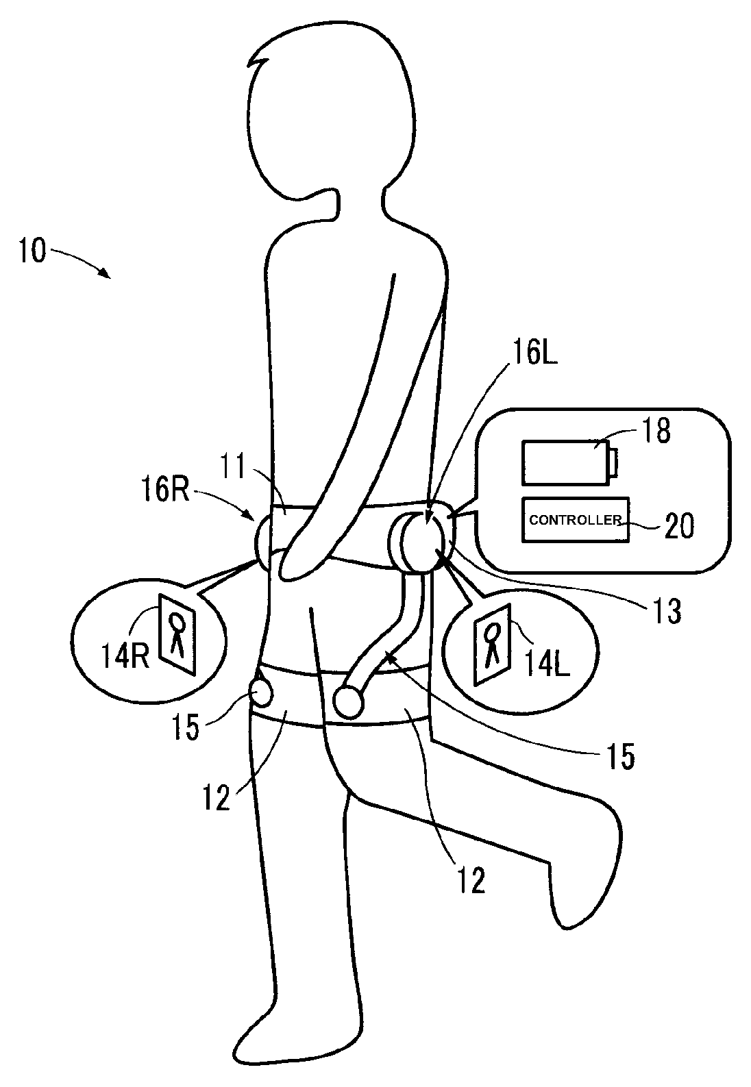
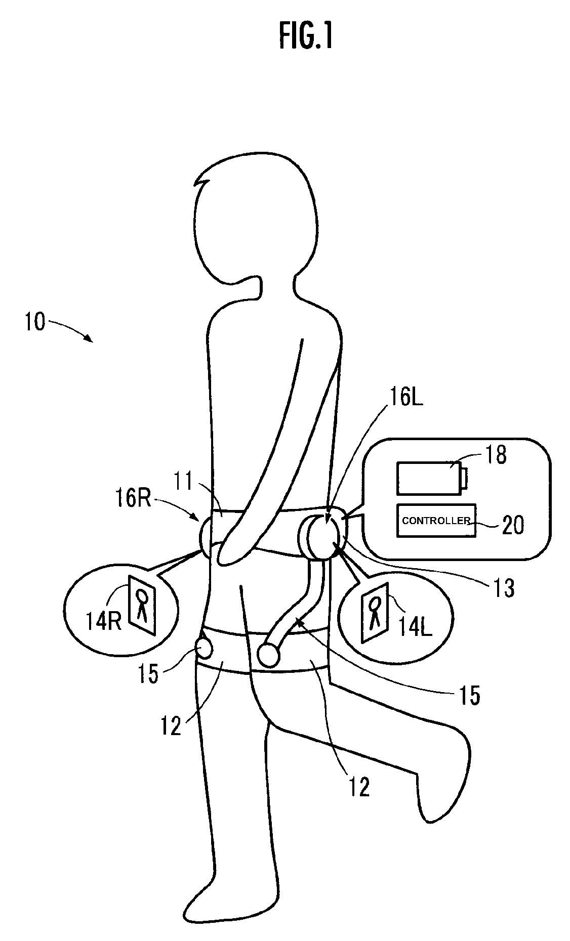
[0049]A first embodiment of the method for controlling the operation of the walking assist device 10 by the controller 20 will be described.

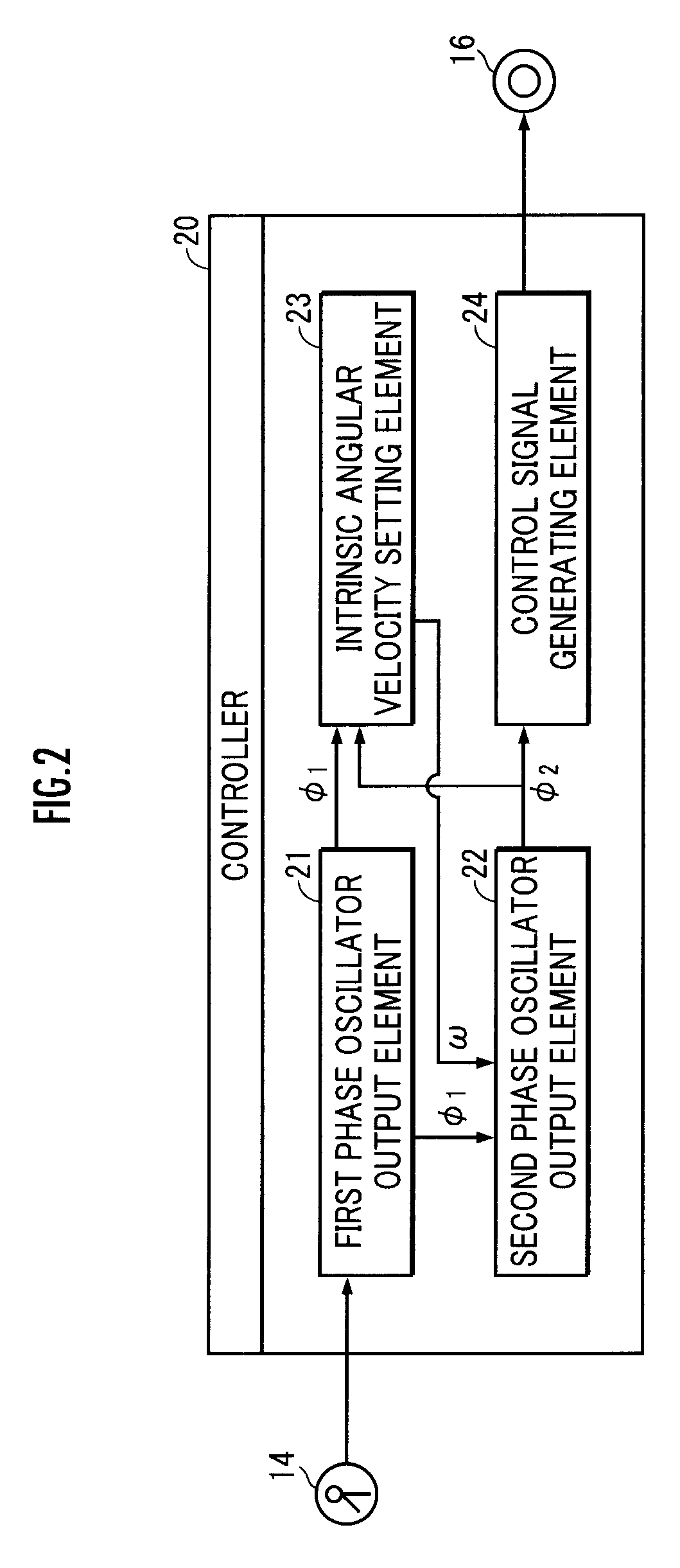
[0050]First, the first phase oscillator output element 21 measures and outputs the phase of a human periodic motion as a first phase oscillator φ1=(φ1L, φ1R) on the basis of an output of the hip joint angle sensor 14 (STEP01 of FIG. 3).

[0051]As illustrated in FIG. 4, if a thigh is regarded as a segment having a hip joint location as one end thereof, then a hip joint angle θ is defined as the angle formed by the segment observed sideways and the basic forehead surface. The basic forehead surface circularly moves about an axial line passing the right and left hip joints as the upper body tilts in the longitudinal direction. The hip joint angle θ is defined such that it takes a positive value when the segment denoting a thigh is in a state located ahead of the basic forehead surface, while ...

second embodiment

(Functions of the Walking Assist Device (Second Embodiment))

[0080]A second embodiment of the method for controlling the operation of a walking assist device 10 by a controller 20 will be described. The method for measuring a first phase oscillator φ1 by a first phase oscillator output element 21 (STEP01 in FIG. 3) and the method for setting an intrinsic angular velocity ω by an intrinsic angle setting element 23 (STEP03 in FIG. 3) are the same as those in the first embodiment, and therefore, the descriptions thereof will be omitted.

[0081]A second phase oscillator output element 22 generates a second phase oscillator φ2 such that a first component thereof, which provides the basis for setting the intrinsic angular velocity ω, and a second component thereof, which provides the basis for generating a control signal η, are different from each other (STEP02 in FIG. 3).

[0082]More specifically, a first component φ21=(φ2L, φ2R) of the second phase oscillator φ2 is determined as the solution...

third embodiment

Functions of the Walking Assist Device (Third Embodiment))

[0091]A third embodiment of the method for controlling the operation of a walking assist device 10 by a controller 20 will be described. The third embodiment is the same as the first embodiment except for the method for generating a control signal η, so that the description of the same arithmetic processing will be omitted.

[0092]The control signal generating element 24 adjusts the values of a first control coefficient C1=(C1L or C1R) and a second control coefficient C2=(C2L or C2R) in relational expressions (141) and (142), respectively, according to relational expressions (143) and (144), respectively, to generate a control signal η (STEP04 in FIG. 3).

C1L=C1R=(½)Carc sin(W0 / LLEG)   (143)

where W0 denotes a desired stride length; LLEG denotes the length of a leg (the distance from a hip joint to a sole of a human being); and C denotes a gain coefficient (a fixed value).

C2L=(½)C(|θLmax|+|θRmin|), C2R=(½)C(|θRmax|+|θLmin|)   (14...


PUM


Abstract

A walking assist device is capable of operating at an appropriate cycle in view of the motion cycle of a human being to be assisted while at the same time reducing the number of control parameters to be adjusted or set. A second phase oscillator, based on which the phase of the periodic operation of each actuator is controlled, is calculated on the basis of the difference between a first phase oscillator, which indicates a phase of the periodic motion of each thigh relative to the upper body of a human being, and the second phase oscillator, and an intrinsic angular velocity. A current intrinsic angular velocity is set by correcting a previous intrinsic angular velocity by an amount based on a previous difference between the first phase oscillator and the second phase oscillator such that the previous difference approaches a desired difference.

Description

BACKGROUND OF THE INVENTION[0001]1. Field of the Invention[0002]The present invention relates to a device adapted to assist a human periodic motion.[0003]2. Description of the Related Art[0004]There has been proposed a technical approach for assisting the periodic motion of a human being by effecting the coordination between a human motion cycle and the operation cycle of a device configured to transmit a force to the human being (refer to Japanese Patent Publication No. 3930399 (Patent Document 1)).[0005]One possible method for reducing the number of parameters to be adjusted or set is to use a phase as a central pattern generator (CPG) model (refer to “Proposal of a motor adaptation mechanism with phase oscillators and trajectory generator” by IIDA, KONDO and ITO at SICE Symposium on Decentralized Autonomous Systems 18, 271-276, 2006. 01.26 (Non-patent Document 1)).[0006]However, oversimplifying a model leads to a higher possibility of the operation cycle of a device becoming inap...

Claims


Application Information

Patent Timeline
Patent Type & Authority Patents(United States)
IPC IPC(8): A61H1/00A61H3/00A61H1/02
CPCA61H3/00A61H1/0244A61H2201/1207A61H2201/163A61H2201/165A61H2201/1642A61H2201/1676A61H2201/5007A61H2201/5069A61H2201/5092G05B2219/45108
Inventor YASUHARA, KEN
Owner HONDA MOTOR CO LTD
Why Eureka
Try Eureka