Radiation imaging system

a radiation imaging and radiation technology, applied in the field of radiation imaging systems, can solve problems such as radiation and/or contamination areas, expose personnel conducting surveys to potentially harmful radiation levels, and contamination

Active Publication Date: 2016-03-22
BATTELLE SAVANNAH RIVER ALLIANCE LLC
View PDF3 Cites 2 Cited by
  • Summary
  • Abstract
  • Description
  • Claims
  • Application Information

AI Technical Summary

Benefits of technology

[0007]One embodiment of the present invention is a radiation imaging system that includes a first casing and a camera disposed inside the first casing. A first field of view through the first casing to the camera exposes the camera to light from outside of the first casing. An image plate is disposed inside the first casing, and a second field of view through the first casing to the image plate exposes the image

Problems solved by technology

The use of radioactive material may result in radiation and/or contamination areas in such areas as reactors, fuel and isotope processing facilities, laboratories, glove boxes, isolators, and other rooms in which the radioactive mater

Method used


Image

  • Radiation imaging system
  • Radiation imaging system
  • Radiation imaging system

Examples


Embodiment Construction

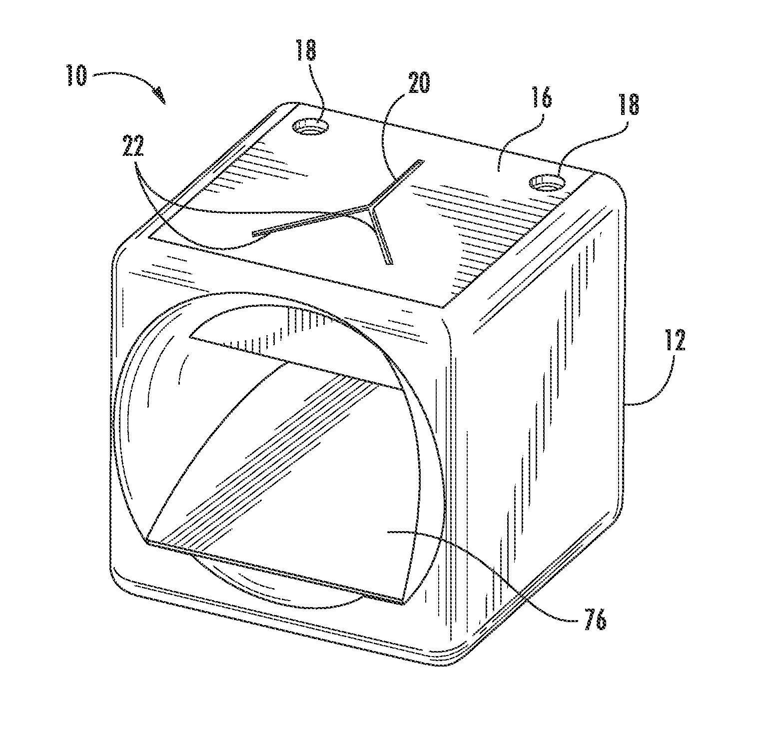
[0028]Reference will now be made in detail to present embodiments of the invention, one or more examples of which are illustrated in the accompanying drawings. The detailed description uses numerical and letter designations to refer to features in the drawings. Like or similar designations in the drawings and description have been used to refer to like or similar parts of the invention. As used herein, the terms “first,”“second,” and “third” may be used interchangeably to distinguish one component from another and are not intended to signify location or importance of the individual components.

[0029]Each example is provided by way of explanation of the invention, not limitation of the invention. In fact, it will be apparent to those skilled in the art that modifications and variations can be made to embodiments of the present invention without departing from the scope or spirit thereof. For instance, features illustrated or described as part of one embodiment may be used on another e...


PUM


Abstract

A radiation imaging system includes a casing and a camera disposed inside the casing. A first field of view through the casing exposes the camera to light from outside of the casing. An image plate is disposed inside the casing, and a second field of view through the casing to the image plate exposes the image plate to high-energy particles produced by a radioisotope outside of the casing. An optical reflector that is substantially transparent to the high-energy particles produced by the radioisotope is disposed with respect to the camera and the image plate to reflect light to the camera and to allow the high-energy particles produced by the radioisotope to pass through the optical reflector to the image plate.

Description

FEDERAL RESEARCH STATEMENT[0001]This invention was made with Government support under Contract No. DE-AC09-08SR22470, awarded by the U.S. Department of Energy. The Government has certain rights in the invention.FIELD OF THE INVENTION[0002]The present invention generally involves a system for imaging radiation, such as high-energy particles (e.g., x-rays or gamma rays) produced by a radioisotope. In particular embodiments, the system may overlay a radiation image with a still or video image to map radioisotopes in a particular area.BACKGROUND OF THE INVENTION[0003]The use of radioactive material may result in radiation and / or contamination areas in such areas as reactors, fuel and isotope processing facilities, laboratories, glove boxes, isolators, and other rooms in which the radioactive material is handled. The location and amount of the resulting radiation and contamination may initially be unknown. Although portable sensors are available to survey the radiation and contamination ...

Claims


Application Information

Patent Timeline
IPC IPC(8): G03B42/00G01T1/08G01T7/00
CPCG01T1/08G01T7/00G01T1/169G01T1/2907G01T1/00
Inventor IMMEL, DAVID M.BOBBIT, III, JOHN T.PLUMMER, JEAN R.FOLSOM, MATTHEW D.SERRATO, MICHAEL G.
Owner BATTELLE SAVANNAH RIVER ALLIANCE LLC
Why Eureka
Try Eureka