
Vacuum storage container

a vacuum storage container and vacuum technology, applied in the field of vacuum storage containers, can solve the problem that conventional mechanical vacuum storage containers cannot automatically pump out air, and achieve the effects of high rotational conversion efficiency, fast vacuum creation, and superior performan

Active Publication Date: 2016-03-29
SHIN HUNG YIH TECH
View PDF5 Cites 11 Cited by
  • Summary
  • Abstract
  • Description
  • Claims
  • Application Information

AI Technical Summary

Benefits of technology

Enables rapid vacuum creation and automatic pressure maintenance during gas leaks, improving upon conventional systems by allowing immediate and automatic ejection of the drawer, enhancing usability and storage efficiency.

Problems solved by technology

Conventional mechanical vacuum storage containers cannot automatically pump air out in case of a gas leakage.
Further, in case of a gas leakage, a conventional electronic vacuum storage container needs to start pumping air out, bringing inconvenience.

Method used


Image

  • Vacuum storage container
  • Vacuum storage container
  • Vacuum storage container

Examples


Embodiment Construction

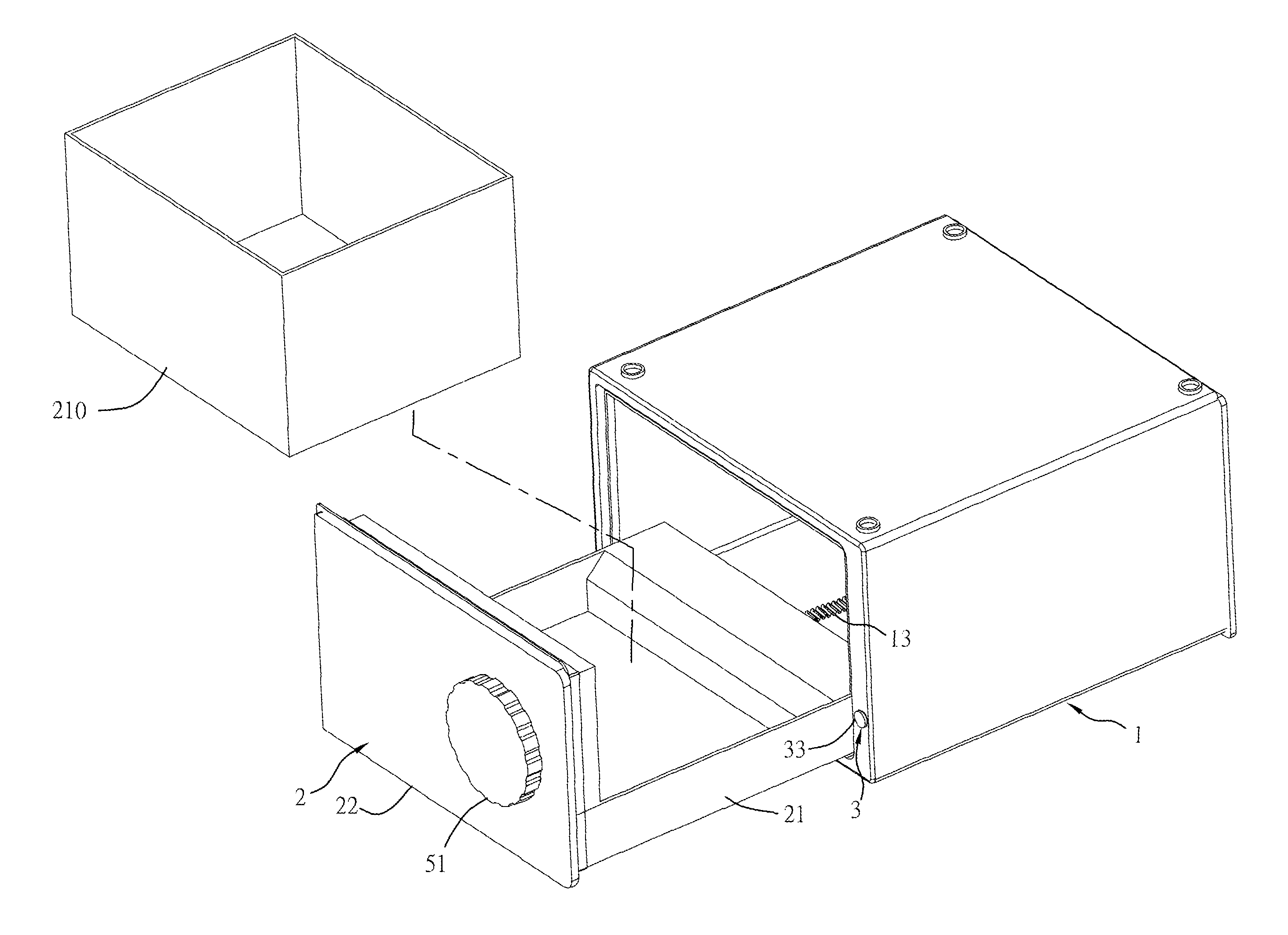
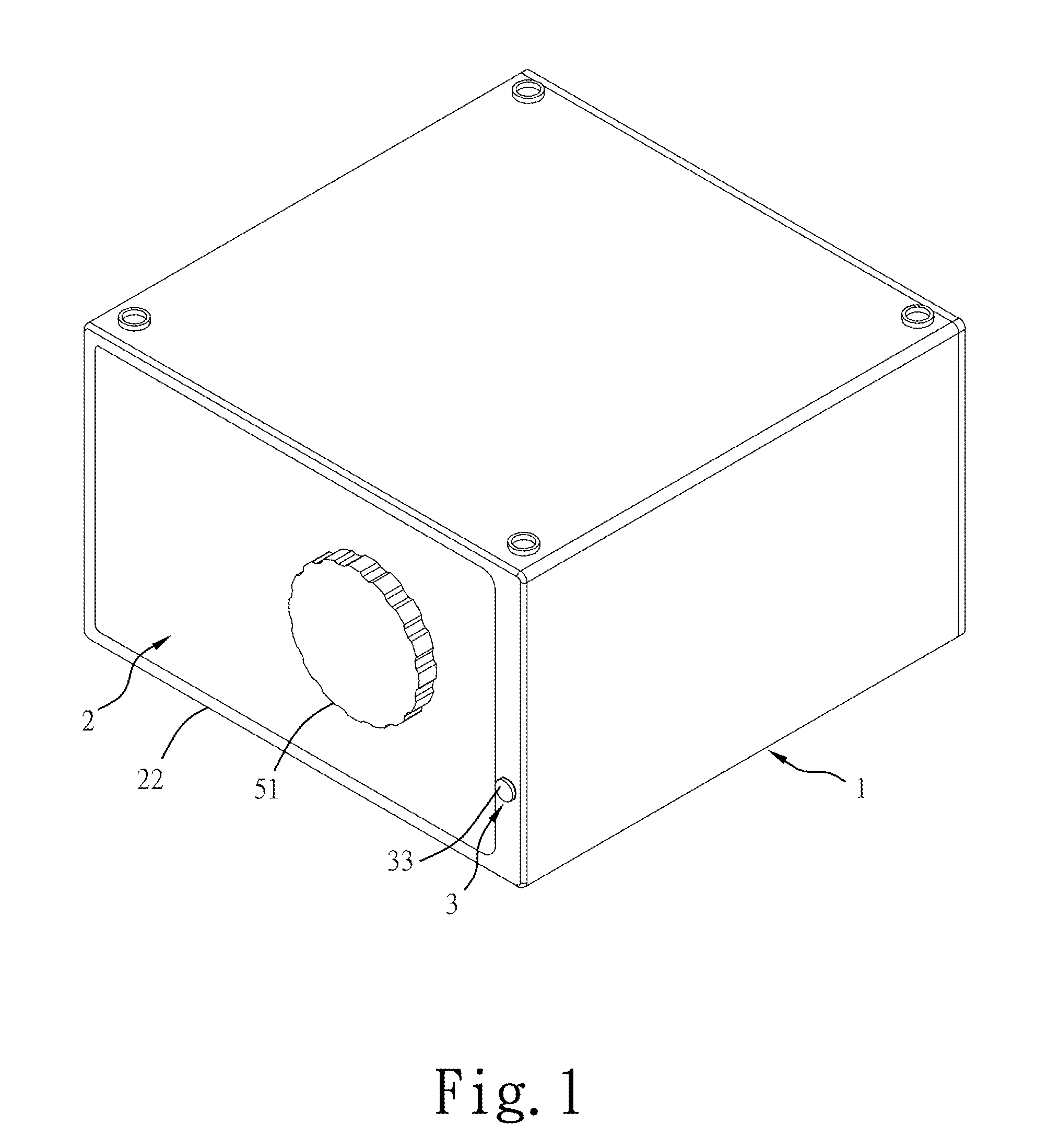
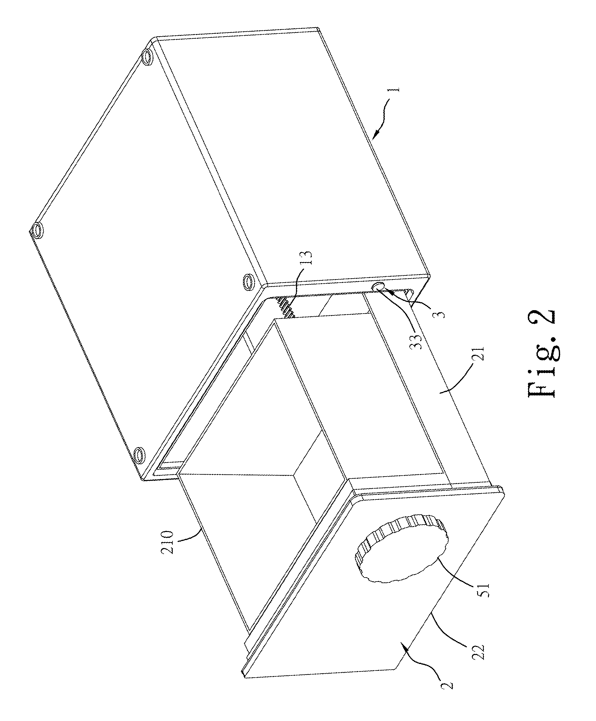
[0030]Referring to FIGS. 1-15, a vacuum storage container in accordance with the present invention is shown. The vacuum storage container comprises a container housing 1 and a drawer 2.

[0031]The container housing 1 is configured for accommodating a drawer 2, enabling the accommodated drawer 2 to be moved in and out between a closed position and an open position. The container housing 1 comprises an operating member control mechanism 3 for locking the drawer 2, for enabling the drawer 2 to be automatically ejected out from the closed position to the open position by an ejection mechanism A (see FIGS. 6-9 and FIGS. 11-14).

[0032]The drawer 2 comprises a drawer body 21 slidably inserted into the container housing 1 (see FIG. 2 and FIG. 3), a door cover 22 located at a front side of the drawer body 21, a rotary knob 51 pivotally mounted in an outer side of the door cover 22 and having a center shaft 511(see FIG. 4) inserted through the door cover 22, a clockwork 52 (see FIG. 4 and FIG. 5...


PUM


Abstract

A vacuum storage container includes a container housing, a drawer mounted in the container housing and movable between a closed position and an open position, a rotary knob pivotally mounted in a door cover of the drawer, clockwork coupled to the rotary knob, a drive gear affixed to the rotary knob, a transmission gear set rotatable by the drive gear, an eccentric wheel rotatable by the transmission gear set, a pumping pump mounted in the drawer and coupled to the eccentric wheel for creating a vacuum in the container housing, an ejection mechanism adapted for ejecting the drawer out of the container housing, and an operating member control mechanism adapted for locking the drawer to the container housing and operable to unlock the drawer for enabling the drawer to be ejected out of the container housing by the ejection mechanism.

Description

BACKGROUND OF THE INVENTION[0001]1. Field of the Invention[0002]The present invention relates to storage container technology and more particularly, to a vacuum storage container, which utilizes an external rotary knob to drive an internal pumping mechanism to create a vacuum.[0003]2. Description of the Related Art[0004]Conventional mechanical vacuum storage containers cannot automatically pump air out in case of a gas leakage. Further, in case of a gas leakage, a conventional electronic vacuum storage container needs to start pumping air out, bringing inconvenience.SUMMARY OF THE INVENTION[0005]The present invention has been accomplished under the circumstances in view. It is the main object of the present invention to provide a vacuum storage container, which achieves a high level of rotational conversion efficiency through the functioning of a drive gear, a transmission gear set and a clockwork, and allows quick creation of a vacuum by means of rotating a rotary knob over a limit...

Claims


Application Information

Patent Timeline
Patent Type & Authority Patents(United States)
IPC IPC(8): B65D81/20
CPCB65D81/2038A47J41/00
Inventor HO, YI-HUNG
Owner SHIN HUNG YIH TECH
Learn More