Supercharge Your Innovation With Domain-Expert AI Agents!

Method for installing a sensing cable along a pipeline

a technology of sensing cables and pipelines, applied in the direction of optical elements, mechanical devices, instruments, etc., can solve the problems of inability to enable current methods, difficult installation of fibre optic sensing cables, and inability to carry out any kind of human access, so as to reduce the risk of sensing cable breakage, and increase the effect of strain

Active Publication Date: 2016-03-29
OMNISENS
View PDF5 Cites 1 Cited by
  • Summary
  • Abstract
  • Description
  • Claims
  • Application Information

AI Technical Summary

Benefits of technology

[0027]The method preferably comprises the step of further providing a reinforcing member in the or each conduit, so that the or each reinforcing member extends inside the conduit, along the length of its respective conduit. The method may comprises the step of providing a reinforcing member only in at least one of the one or more conduits. The reinforcing member may be a cable (referred to as a reinforcement cable), rod or rope member for example. Preferably reinforcing member is a metallic cable. The reinforcing member will help to prevent the conduit from collapsing if / where the conduit rubs, or hits against, the walls of the bore hole. Preferably the or each reinforcing member will be positioned adjacent to fiber optic sensing cable which extends inside the conduit, along the length of the conduit. The method may comprise the step of attaching the or each fiber optic sensing cable to a respective fiber optic sensing cable. Most preferably the or each fiber optic sensing cable in the each conduits is connected to a respective reinforcing member which extends inside the conduit, along the length of the conduit.
[0037]The step of moving the pipeline assembly into the bore hole may comprises the step of pulling the pipeline assembly through the bore hole using a pulling line, using a protective cover which are provided on the attachment head to prevent the tracks from contacting walls of the bore hole. The protective cover may also help to maintain a gap between the walls of the bore hole and the one or more conduits as the pipeline assembly is pulled through the bore hole.
[0042]The cover may further extend over the means for connecting. The cover in this case will prevent dirt from reaching the means for connecting. The cover may also provide protection for the one or more tracks and the parts of the conduits which are contained in the tracks. The cover may also serve to maintain a gap between the pipeline assembly and walls of a bore hole.
[0054]The or each conduit may each comprise a reinforcing member which extends inside the conduit, along the length of its respective conduit. The reinforcing member may be a metallic cable, rod or rope member for example. The reinforcing member will help to prevent the conduit from collapsing if / where the conduit rubs, or hits against, the walls of the bore hole. The fiber optic sensing cable(s) which have been moved into the or each conduit is attached to the metallic cable which is located inside the conduit. This attachment may be achieved by means of glue, straps or bands or any other suitable means. The reinforcing member is preferably a metallic cable. Preferably the metallic cable is a steel cable. The metallic cable may run adjacent a fiber optical sensing cable or pulling line which is located within the respective conduit. The metallic cable may also be attached to an attachment head which is provided at an end of a pulling cable. The metallic cable may be attached to the attachment head which is provided at an end of a pulling cable using hooks (as described later in the description) or any other suitable attachment means. This provides a stronger pulling force for the sensing / metallic cable assembly and reduces the risk of sensing cable breakage. Due to the rubbing force, the conduit tends to move back and doing so add strain by friction on the sensing cable inside. The provision of the metallic cable ensures that part of the load due to the conduit movement is taken by the metal cable thus reducing the strain on the sensing cable. The metallic cable therefore provides structural support which reduces the risk of the sensing cable becoming damaged. Preferably, the sensing cable is attached regularly (for instance every 2 to 5 m) to the metallic cable so that strain on the sensing cable is regularly transferred to the metallic cable. This further reduces the risk for damaging the cable. This means that straps, bands, or tape which is used to attach one or more conduits to the pipe are provided at regular intervals along the length of the pipe. For example straps, bands, or tape which hold the one or more conduits against the outer-surface of the pipe may be provided every 2-5 m along the length of the pipe.

Problems solved by technology

It is difficult to install fibre optic sensing cables, such as those shown in FIG. 1, along pipelines which are installed in horizontal bore holes.
However, current methods are not practical to enable this since the diameter of the bore holes are only marginally larger than the diameter of the pipeline.
Moreover, the bore hole is full of bentonite (fluid used to lubricate and refrigerate the drill head and reamers before and after the pull) which makes any kind of human access impossible.
Furthermore due to the tight space between the pipeline and the walls of the bore hole, it is not possible, or at least very difficult, to thread a fibre optic sensing cable along the space between the pipeline and the walls of the bore hole.
However, this would increase the distance between the pipeline and fibre optic sensing cable thus reducing the sensing capacities of the fibre optic sensing cable.
Moreover, an additional bore hole represents a significant additional cost to the sensing system.

Method used


Image

  • Method for installing a sensing cable along a pipeline
  • Method for installing a sensing cable along a pipeline
  • Method for installing a sensing cable along a pipeline

Examples


Embodiment Construction

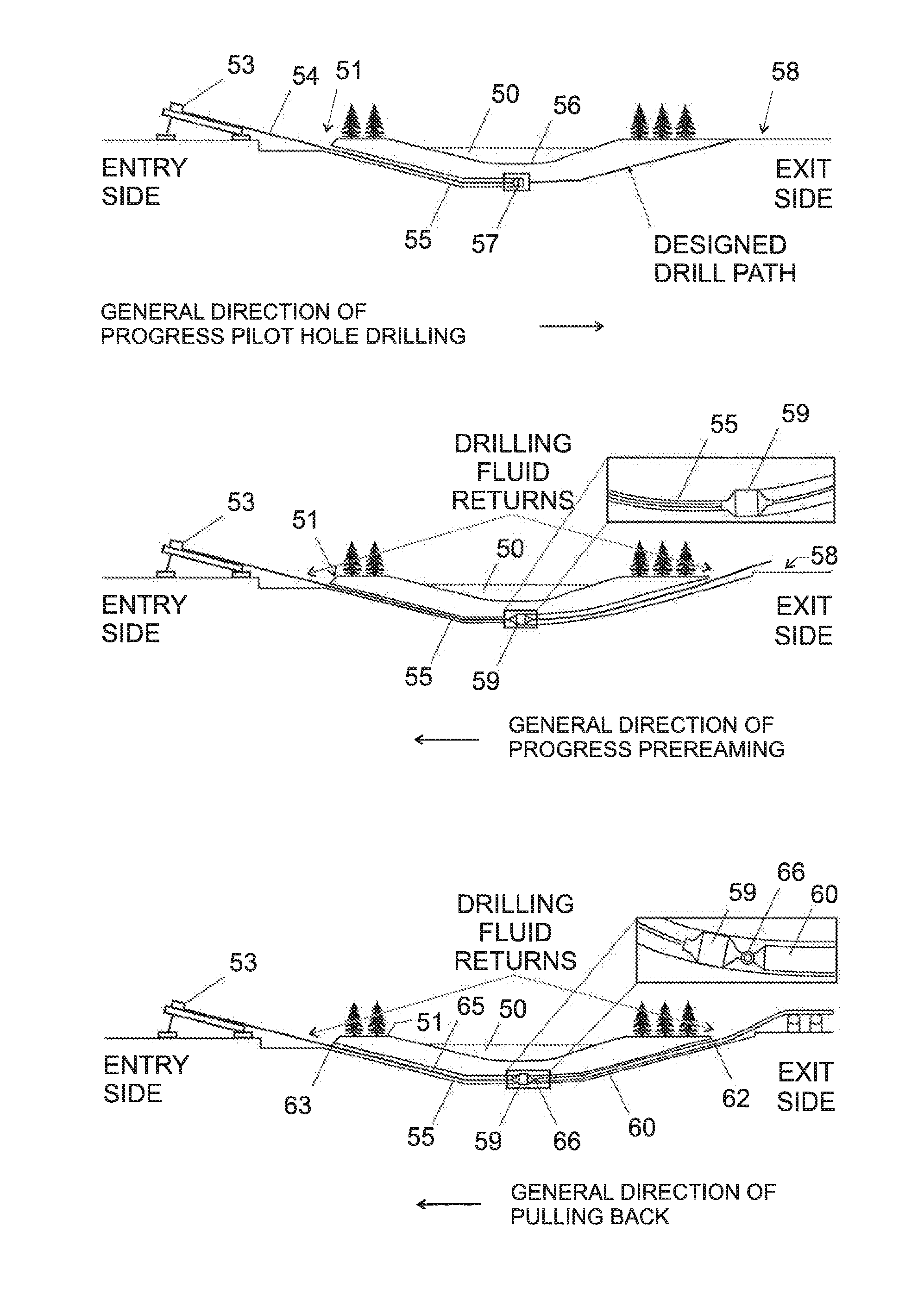
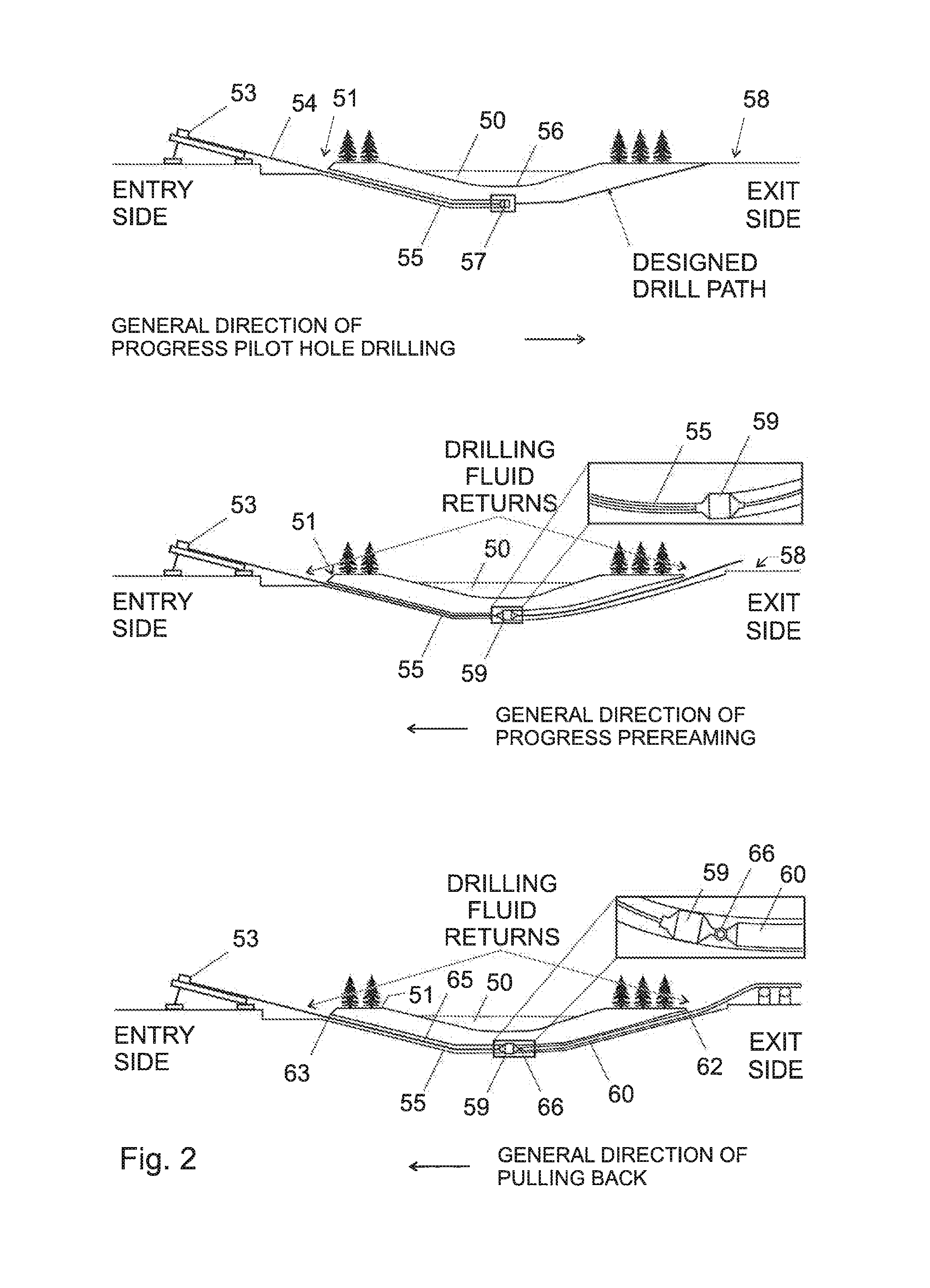
[0067]The present invention provides a mean of solving the problems associated with installation of fiber optic sensing cable along the HDD. In particular the present invention eliminates the risk of damage to fiber optic sensing cable or cause the fiber optic sensing cable to become detached from the and pipe, when a pipeline assembly is being installed in a horizontal bore. It will be understood that the present invention may use all or some of the steps of the known drilling and installation method illustrated in FIG. 2; however in the present invention additional steps are performed which mitigate the afore-mentioned problems.

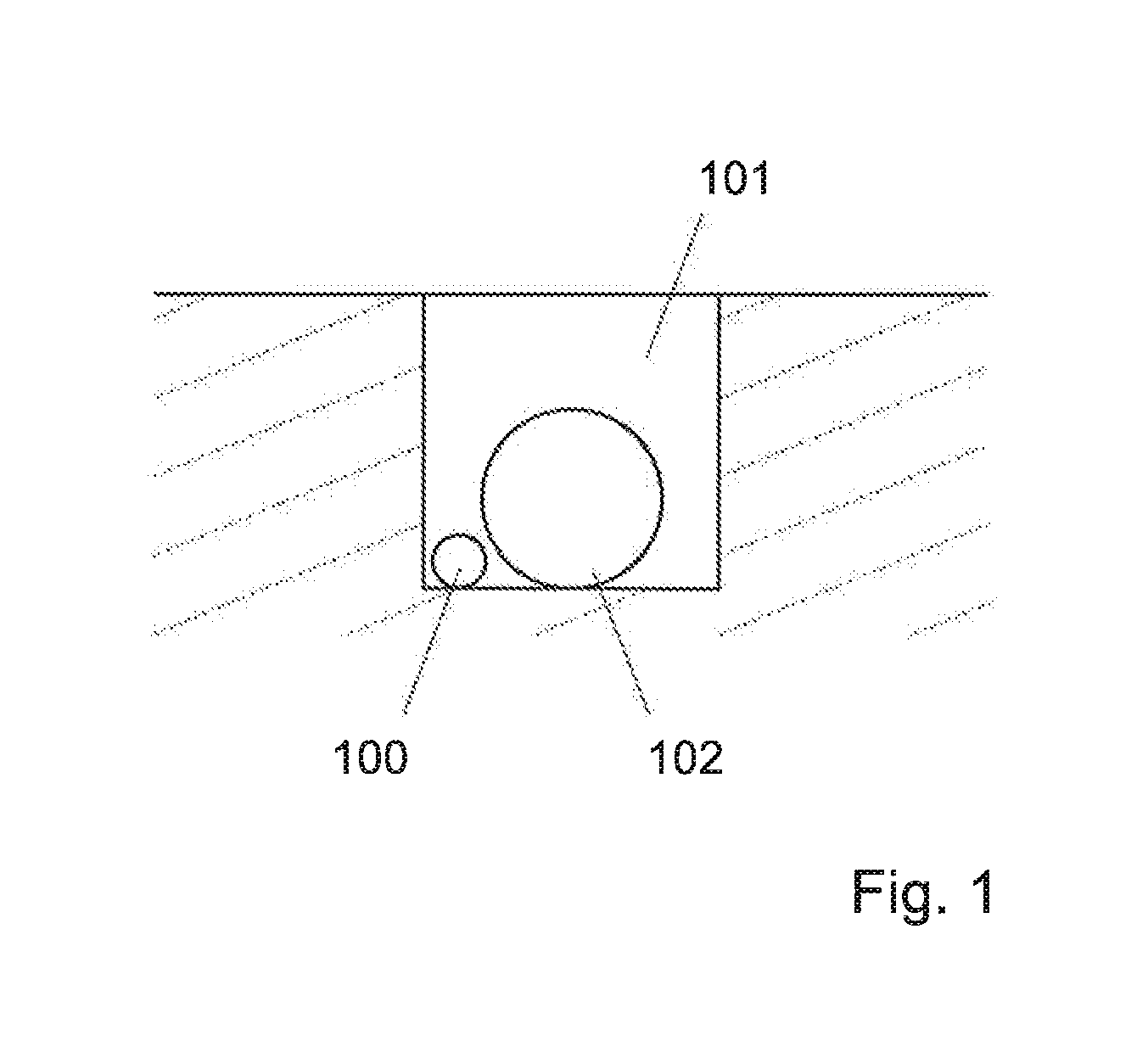
[0068]The present invention involves providing a mechanically strong (heavy duty) conduit which has a smaller diameter compared with the diameter of the pipeline, which is attached to an outer-surface of the pipeline. The fiber optic sensing cable is threaded through the conduit. Preferably the conduit has an inner diameter which is 2-5 times the diameter o...


PUM


Abstract

According to the present invention there is provided a method for installing a sensing cable along a pipeline, comprising the steps of, attaching one or more conduits to an outer-surface of a pipe which is to be installed in a bore hole to form a pipeline assembly; moving the pipeline assembly into the bore hole; moving an fiber optic sensing cable into one or more of the conduit after the pipeline assembly has been moved into the bore hole or before the pipeline assembly has been moved into the bore hole. There is further provided a corresponding pipeline assembly, and a attachment head which can facilitate attachment of a pulling line to a pipeline assembly.

Description

FIELD OF THE INVENTION[0001]The present invention concerns a method for installing a sensing cable along a pipeline and in particular to a method for installing a sensing cable along a pipeline which is installed in a horizontal directional drilling section. There is further provided a corresponding pipeline assembly, and a attachment head which can facilitate attachment of a pulling line to a pipeline assembly.BACKGROUND[0002]Efficient pipeline monitoring can be achieved with the help of optical based distributed sensing method and provides long term information on the pipeline integrity[0003]As is shown in FIG. 1, usually, a fibre optic sensing cable 100 is installed in the trench 101 along the pipeline 102; once backfilled, the fibre optic sensing cable 100 lies within close vicinity of the pipeline 102.[0004]In the configuration shown in FIG. 1, ground movement around the pipeline 102 can be measured for instance using Brillouin based (for instance BOTDA, BOTDR etc) based or Ray...

Claims


Application Information

Patent Timeline
Patent Type & Authority Patents(United States)
IPC IPC(8): G02B6/00F16L9/18G02B6/50G02B6/44
CPCF16L9/18G02B6/504G02B6/4465G02B6/545
Inventor DUTOIT, DANADOS, SANTOS, BORDA, CARLOS, JOSENIKLES, MARC
Owner OMNISENS
Features
  • R&D
  • Intellectual Property
  • Life Sciences
  • Materials
  • Tech Scout
  • Unparalleled Data Quality
  • Higher Quality Content
  • 60% Fewer Hallucinations
Learn More