Extended length flow conditioner

a flow conditioner and extended length technology, applied in the direction of liquid/fluent solid measurement, volume indication and recording device, etc., can solve the problems of difficult to measure the fluid flow rate in a consistently accurate and repeatable manner, asymmetrical, unstable configuration, and long lengths of straight pipes, so as to minimize or eliminate swirling, the effect of minimizing or preventing any rotation or rocking

Active Publication Date: 2016-03-29
CANADA PIPELINE ACCESSORIES
View PDF34 Cites 4 Cited by
  • Summary
  • Abstract
  • Description
  • Claims
  • Application Information

AI Technical Summary

Benefits of technology

[0010]An advantage of the flow conditioner according to the present invention is that it minimizes or eliminates swirl and provides a fully developed velocity flow profile.
[0011]Another advantage of the flow conditioner according to the present invention is that it stays tight in a pipe, thereby substantially minimizing or preventing any rotating or rocking that could cause an installation pin to dislodge.

Problems solved by technology

However, having long lengths of straight pipe is impractical and cost prohibitive.
As a result, meter station piping often contains elbows, tees, valves and other assemblies that distort the flow profile into an asymmetric, unstable, and distorted configuration.
This makes it very difficult to measure the fluid flow rate in a consistently accurate and repeatable manner.

Method used


Image

  • Extended length flow conditioner
  • Extended length flow conditioner
  • Extended length flow conditioner

Examples


Embodiment Construction

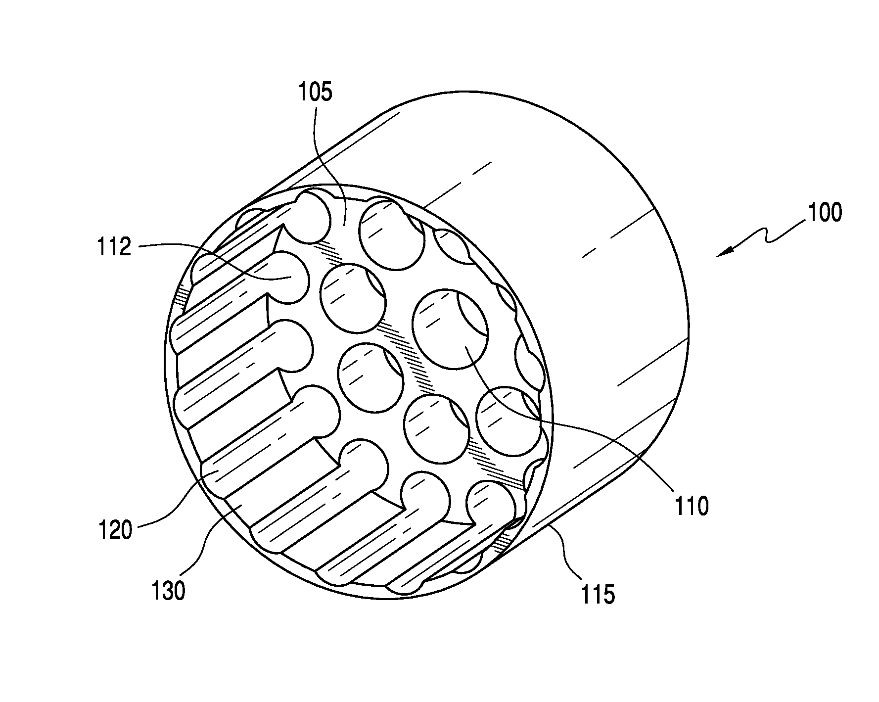
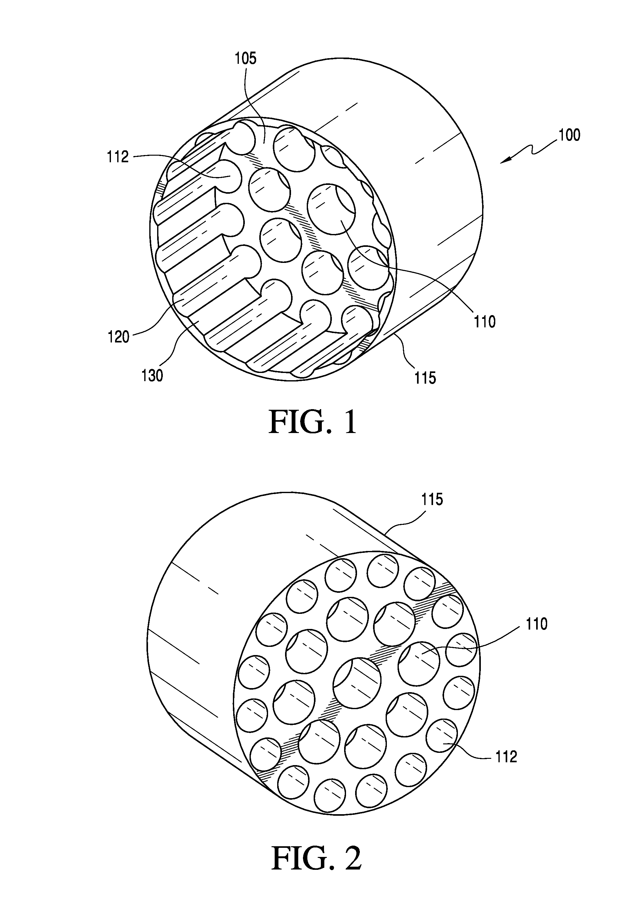
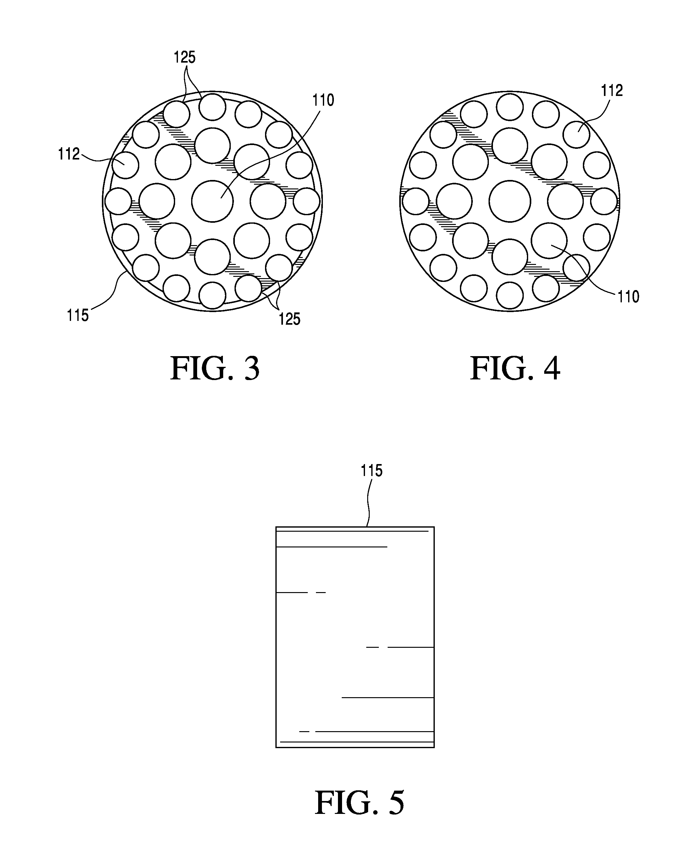
[0024]As shown in FIGS. 1-8, a flow conditioner 100 according to the present invention comprises a single disk 105 comprising an array of holes 110 and having an outer ring of holes 112. A section 115 extends longitudinally from an outer circumference of the disk and comprises bores 120 that at least partially follow the contour or pattern of the outer ring of holes 112, that is, a portion of an outer ring of holes or apertures is bored along the extended section.

[0025]Thus, the extended section 115 comprises a plurality of bores 120, each bore 120 extending from an outer hole and at least partially following a circumference of the outer hole. Between the holes of the outer ring of holes 112, along a surface of the disk 105, there are opposing sharp or pointed corners 125 (FIG. 3 and FIG. 7). Flat sections 130 extend longitudinally along the extended section 115 between bores 120, as illustrated in FIG. 1 and FIG. 6.

[0026]The flow conditioner may be installed in any pipe having insi...


PUM


Abstract

A flow conditioner includes 1) a single disk comprising an array of holes and having an outer ring of holes, and 2) a section extending longitudinally from an outer circumference of the disk and comprising bores that at least partially follow the contour or pattern of the outer ring of holes.

Description

[0001]This application claims priority to U.S. provisional patent application Ser. No. 61 / 753,512 filed in the U.S. Patent and Trademark Office on Jan. 17, 2013, the entirety of which is incorporated herein by reference.FIELD OF THE INVENTION[0002]The present invention relates to fluid flow measurement components used in oil and gas pipelines. More particularly, the present invention relates to a flow conditioner having an extended length around an outer set of holes or apertures.BACKGROUND OF THE INVENTION[0003]Pipelines are used to transport fluids in various industries, including chemical, oil and gas, and manufacturing. These industries use processes that require fluid flow rates to be accurately measured. These measurements are performed at locations known as meter stations using a variety of different meter types. These meters function in different ways, they can use: differential pressure of the fluid across an obstruction, ultrasonic signal travel times, turbine blade rotati...

Claims


Application Information

Patent Timeline
Patent Type & Authority Patents(United States)
IPC IPC(8): G01F3/12G01F15/00G01F15/06F15D1/02F16L55/027
CPCF15D1/025F16L55/02763G01F15/00F16L55/02718
Inventor SAWCHUK, DANIEL, A.SELIRIO, REGINALD
Owner CANADA PIPELINE ACCESSORIES
Why Eureka
Try Eureka