Bridging type noise elimination and air guide passage for vehicle air conditioner compressor

A vehicle air-conditioning, bridge-type technology, applied in mechanical equipment, machines/engines, liquid fuel engines, etc., can solve the problems of heavier parts, reduced performance, and more momentum.

Pending Publication Date: 2021-05-18
CHONGQING BUILDING VEHICLE USE AIR CONDITIONER
View PDF0 Cites 0 Cited by
  • Summary
  • Abstract
  • Description
  • Claims
  • Application Information

AI Technical Summary

Problems solved by technology

According to the principle of vibration, the aerodynamic noise emitted by gas flow is caused by many factors such as turbulence (vortex is a form of turbulence), pressure difference (pressure fluctuation), vortex breakage, etc., and the turbulent flow is chaotic and produces shear. The flow will dissipate more momentum and cause flow loss, that is, the kinetic energy of the fluid is converted into heat energy, thereby reducing the flow rate and reducing the performance of the compressor
At the same time, the high-speed gas is ejected from the exhaust port of the cylinder body and hits the

Method used


Image

  • Bridging type noise elimination and air guide passage for vehicle air conditioner compressor
  • Bridging type noise elimination and air guide passage for vehicle air conditioner compressor
  • Bridging type noise elimination and air guide passage for vehicle air conditioner compressor

Examples


Embodiment Construction

[0027] Embodiments of the present invention will be described in further detail below in conjunction with the accompanying drawings.

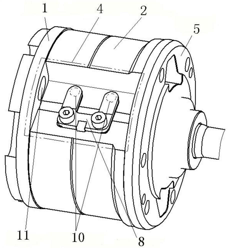
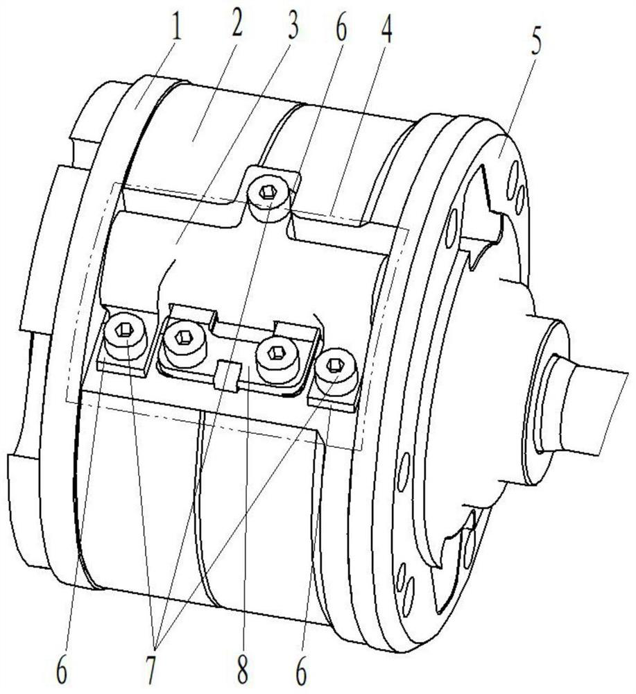
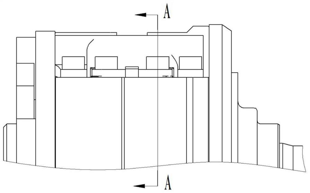
[0028] Such as Figure 1-Figure 7 The vehicle air conditioner compressor shown in the bridging muffler air guide passage is arranged inside the air conditioner compressor. The air conditioner compressor includes a casing, a rear end plate 1, a cylinder body 2 and a front end plate 5 arranged in the casing. The housing, the front end plate 5, the rear end plate 1 and the cylinder body 2 are enclosed to form a primary muffler cavity 4, the cylinder body 2 is equipped with a valve assembly 8, and also includes a muffler air duct 3, the muffler chamber The air guide pipe 3 is set at the position of the first-level muffler cavity 4, and is fixedly connected with the cylinder body 2 by screws 7. The inside of the muffler air guide pipe 3 is provided with a cavity 31, which is connected with the cylinder body exhaust hole 10 and the rear end plate air...


PUM


Abstract

The invention provides a bridging type noise elimination and air guide passage for a vehicle air conditioner compressor. The bridging type noise elimination and air guide passage is arranged in the air conditioner compressor. The air conditioner compressor comprises a shell, a rear end plate, a cylinder body and a front end plate, wherein the rear end plate, the cylinder body and the front end plate are arranged in the shell. A first-stage noise elimination cavity is formed by the shell, the front end plate, the rear end plate and the cylinder body in an enclosed manner. A valve assembly is arranged on the cylinder body. The bridging type noise elimination and air guide passage further comprises a noise elimination and air guide pipe. The noise elimination and air guide pipe is arranged at the position of the first-stage noise elimination cavity and fixedly connected with the cylinder body. A cavity is formed in the noise elimination and air guide pipe and communicates with a cylinder body exhaust hole and a rear end plate air inlet hole. High-pressure air in the compressor is exhausted from the cylinder body exhaust hole and then directly enters the built-in noise elimination and air guide pipe, the high-pressure air directly enters the air inlet hole of the rear end plate after passing through the cavity of the noise elimination and air guide pipe, and the bridging type noise elimination and air guide passage is formed. According to the bridging type noise elimination and air guide passage, the bridging type noise elimination and air guide passage arranged in the first-stage noise elimination cavity is designed, the whole high-pressure cavity is simplified into a pipeline connection type passage, a new air flowing path is formed, it is guaranteed that the pressure gradients of the high-pressure cavity are similar, and pressure losses are reduced.

Description

technical field [0001] The invention relates to the technical field of noise elimination for air conditioner compressors, in particular to a bridge-connected noise elimination air guide passage for vehicle air conditioner compressors. Background technique [0002] At present, the gas of the rotary vane compressor is compressed into high-temperature and high-pressure gas in the compression chamber of the cylinder body, and then discharged at high speed through the exhaust hole of the cylinder body, and enters the first-stage anechoic chamber after opening the valve assembly. into the air intake on the rear end panel. Due to the large sudden change of the flow caused by the gas flowing in the cylinder exhaust hole (small diameter) in the first-stage muffler chamber, a large pressure gradient change is formed and affected by the structure of the valve assembly and the large open space of the first-stage muffler chamber, resulting in The cooling capacity of the compressor (here...

Claims


Application Information

Patent Timeline
IPC IPC(8): F04C29/06F04C29/12
CPCF04C29/06F04C29/12
Inventor 刘进陶平安刘红梅段威林
Owner CHONGQING BUILDING VEHICLE USE AIR CONDITIONER
Why Eureka
Try Eureka