A filling device in the sorting section of a flotation column

A filling device and flotation column technology

Active Publication Date: 2019-04-02
CHINA UNIV OF MINING & TECH
View PDF4 Cites 0 Cited by
  • Summary
  • Abstract
  • Description
  • Claims
  • Application Information

AI Technical Summary

Problems solved by technology

However, in this kind of mixed filling, the holes on the sieve plate are evenly arranged, that is, the hole diameter and hole spacing are the same, while the bubble dispersion in the column flotation section is in an uneven state, and the rectification effect of the single-layer sieve plate is limited, so usually There will be more than six layers of sieve plates, which will reduce the effective volume of the flotation column, and the cost is high, and the later maintenance is difficult

Method used


Image

  • A filling device in the sorting section of a flotation column
  • A filling device in the sorting section of a flotation column
  • A filling device in the sorting section of a flotation column

Examples


Embodiment Construction

[0022] The present invention will be further described below in conjunction with accompanying drawing.

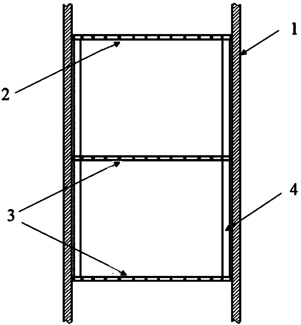
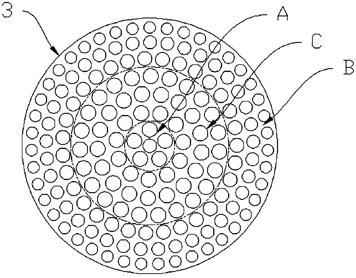
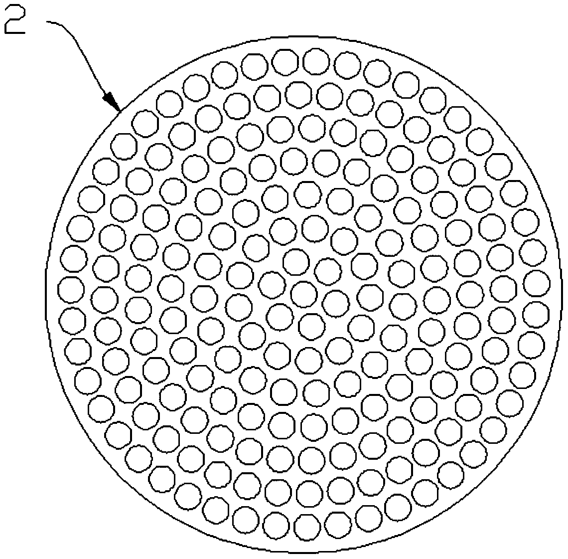
[0023] Such as Figures 1 to 3 As shown, a filling device in the sorting section of a flotation column includes a sieve layer arranged in the flotation column 1 that matches the size of the flotation column, and the sieve layer includes a layer arranged on the upper part of the flotation column Uniform sieve plates 2 and one to three layers of non-uniform sieve plates 3 arranged at the lower part of the flotation column are supported by diversion tubes 4 between adjacent two layers of sieve plates; the non-uniform sieve plates 3 are arranged in different radial directions The diameter of the circular hole, wherein the diameter of the circular hole in the central area A and the edge area B of the sieve plate is smaller than that of the area C between them, the diameter of the circular hole from the A area to the C area gradually becomes larger, and the C area to the B area ...


PUM


Abstract

The invention discloses a filling device in a separation section of a flotation column. The filling device comprises a sieve plate layer which is arranged in a flotation column and is matched with theflotation column in size, wherein the sieve plate layer comprises a layer of uniform sieve plate arranged at the upper part of the flotation column and one to three layers of non-uniform sieve platesarranged at the lower part of the flotation column; two adjacent layers of sieve plates are supported by a diversion round pipe; round holes with different apertures are formed in the non-uniform sieve plates along the radial direction; the apertures of the round holes in a central region A and a sieve plate edge region B are relatively small, and the apertures of the round holes in a region C between the central region A and the sieve plate edge region B is relatively large; the apertures of the round holes from the region A to the region C are gradually increased, and the apertures of the round holes from the region C to the region B are gradually decreased; and round holes with same apertures are uniformly formed in the uniform sieve plate along the radial direction. According to the filling device in the separation section of the flotation column, due to regular arrangement of fluid, distribution of air bubbles can be more uniform, and the rectification effect is better, so that the separation effect is effectively enhanced; and by increase of the effective volume in the floatation column, the ore pulp flux is increased, and blocking is prevented.

Description

technical field [0001] The invention relates to a flotation column, in particular to a filling device in the sorting section of the flotation column, and belongs to the technical field of mineral processing equipment. Background technique [0002] The cyclone-static micro-bubble flotation column is a new type of column separation equipment with my country's independent intellectual property rights. Its unique cascade optimized separation structure makes the flotation column technology successfully applied in my country's mineral separation For the flotation of fine-grained minerals. Cascade optimization separation includes three parts: column flotation, cyclone separation and pipe flow mineralization, which correspond to the column flotation section, cyclone section and pipe flow section of the flotation column respectively. The main body of the equipment is cylindrical, and the column flotation section and the cyclone separation section are directly connected in an up and d...

Claims


Application Information

Patent Timeline
Patent Type & Authority Patents(China)
IPC IPC(8): B03D1/24
Inventor 王利军陈朱应闫小康
Owner CHINA UNIV OF MINING & TECH
Why Eureka
Try Eureka