Firearm bump stock assembly

a technology for bumping stock and firing guns, which is applied in the direction of weapon components, weapons, launching weapons, etc., can solve the problems of significant negative impact on the ability of users to aim a firearm, and achieve the effect of reducing time, increasing fire rate efficiency of firearms, and reducing the amount of tim

Inactive Publication Date: 2016-03-29
MARCOTTE BRYANT A
View PDF2 Cites 0 Cited by
  • Summary
  • Abstract
  • Description
  • Claims
  • Application Information

AI Technical Summary

Benefits of technology

[0009]The present invention comprises a firearm bump-stock assembly that can increase fire rate efficiency of a firearm by being able to reduce an amount of time between pulling of a trigger on a firearm and reloading of a new bullet into a chamber of said firearm, thereby allowing said firearm to reload, and ultimately, fire more quickly, while maintaining accuracy of said firearm.
[0010]In a preferred embodiment, the bump stock assembly of the present invention can be used to mount and support a conventional semi-automatic firearm, and thus, is compatible with a variety of types of semi-automatic firearms, including, but not limited to firearms comprising a picatinny rail or a tactical rail underneath a hand guard, or firearms comprising an AR-type buffer tube. Ultimately, the bump stock assembly of the present invention is more reliable than conventional bump fire systems and is beneficial to any user that has difficulty in supporting and holding a firearm, such as, for example, a user who is disabled or a user who lacks strength capabilities.
[0012]In a preferred embodiment, said firearm mount frame attachably affixes to a body of a firearm, thus stabilizing said firearm, and ultimately, maintaining accuracy and aim of said firearm. Said firearm mount frame is joined and affixed to a stand assembly, thereby further holding and securing said firearm when said firearm is in use.
[0013]In a preferred embodiment, said bump stock assembly of the present invention allows a user to apply a consistent amount of forward pressure to a rear end of a buffer tube, thereby causing the firearm to slide forward, and thus, causing a trigger to be actuated by compressing against a stationary rigid member, such as, for example, a cross-bolt, or any other similar rigid member having desired characteristics. Said cross-bolt connecting through said trigger guard allows said firearm to be able to discharge, as said firearm is pressed forward and said trigger is compressed against said cross-bolt. Then, said firearm's discharge recoils said firearm in a backwards motion, thereby allowing the trigger to reset, and thus, fire again from said forward consistent pressure that is caused by the user's thumbs and / or hands and the constant contact of the trigger with the cross-bolt. This results in a simulation of a fully automatic discharge from a semi-automatic firearm.
[0014]Thus, as a result, the bump stock assembly of the present invention allows a user to be able to increase a firearm's rate of fire, while simultaneously allowing said user to maintain accuracy of said firearm.

Problems solved by technology

Consequently, conventional bump fire systems have a significant negative impact on a user's ability to aim a firearm, and thus, the accuracy of said firearm, due to a necessary jerking motion of said firearm.

Method used


Image

  • Firearm bump stock assembly
  • Firearm bump stock assembly
  • Firearm bump stock assembly

Examples


Embodiment Construction

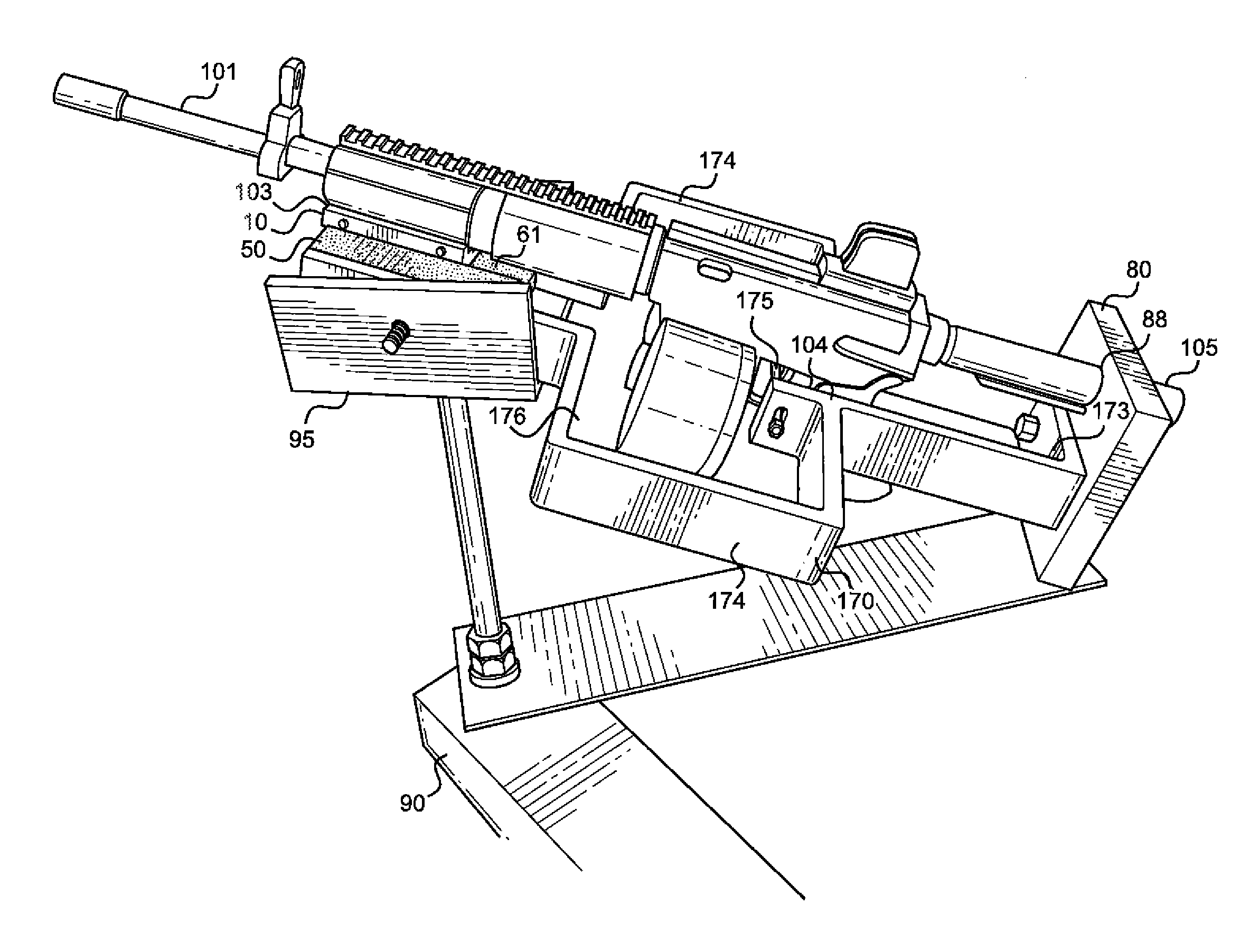
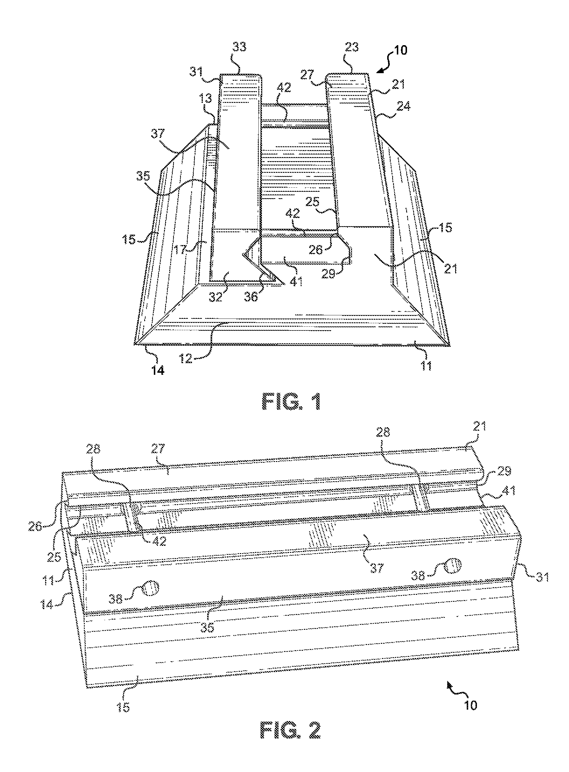
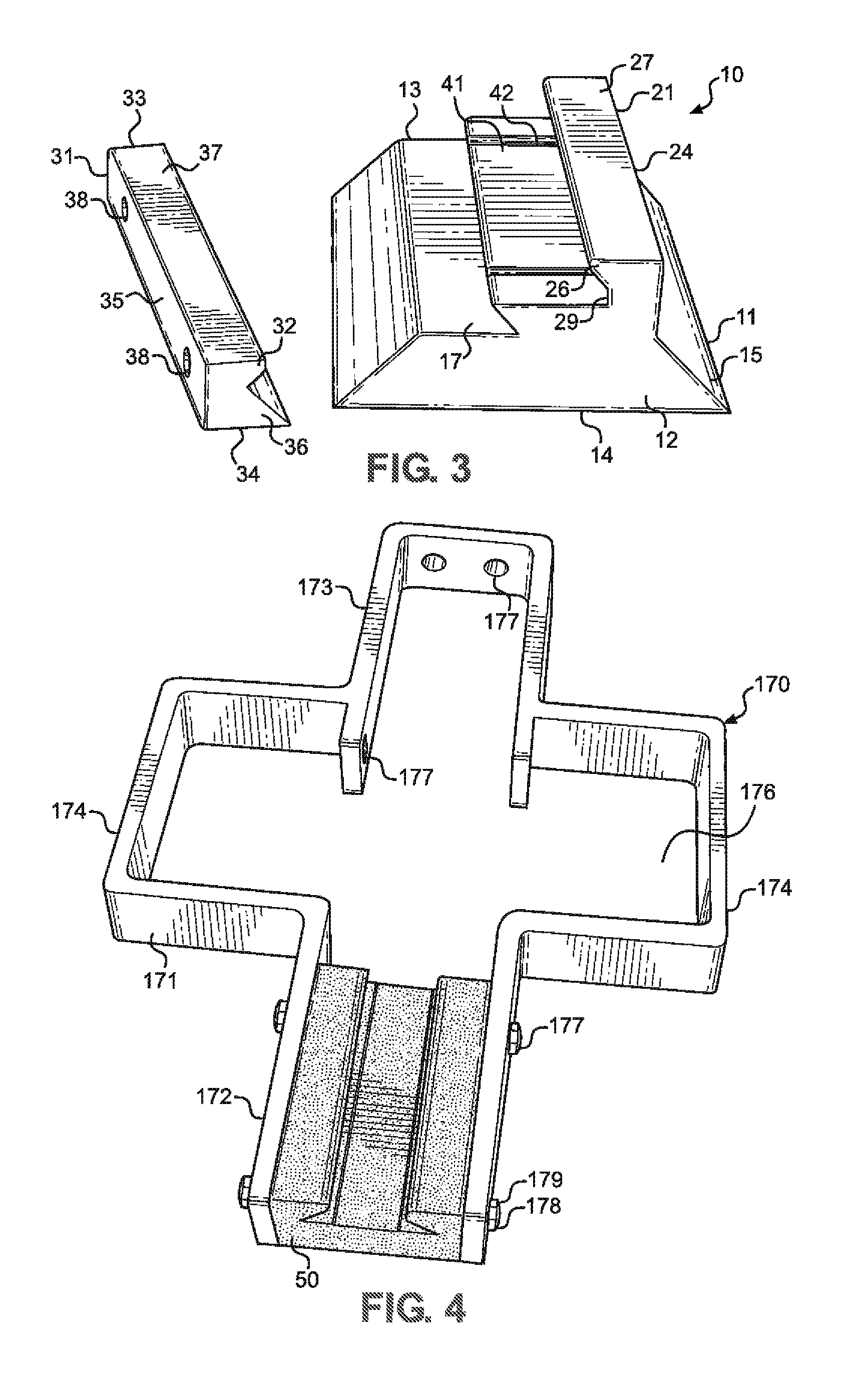
[0035]Referring to the drawings, FIG. 1 depicts a front perspective view of a preferred embodiment of a firearm receiving assembly 10 of the present invention in a connected configuration, while FIG. 3 depicts a front perspective view of a preferred embodiment of a firearm receiving assembly 10 of the present invention in an exploded or disconnected configuration.

[0036]FIG. 1 depicts a front perspective view of a firearm receiving assembly 10 of the present invention generally comprising receiver member 11 and receiver attachment member 31 in a connected configuration. As depicted in FIG. 1, receiver member 11 and receiver attachment member 31 can be manufactured from a solid structural material, such as, for example, a metal material, or any other substantially solid material exhibiting desired characteristics.

[0037]In a preferred embodiment, receiver member 11 generally comprises a substantially trapezoidal-shaped configuration having a front end 12 and a rear end 13. Receiver mem...


PUM


Abstract

A firearm bump stock assembly provides a mount and support for a conventional semi-automatic firearm. The firearm bump stock assembly beneficially provides a user with the ability to increase the fire rate efficiency of a firearm by reducing the amount of time between pulling of a trigger on a firearm and reloading of a new bullet into a chamber of said firearm, thus allowing said firearm to be reloaded and fired more rapidly. The firearm bump stock assembly also beneficially provides a user with the ability to maintain accuracy of said firearm and to easily aim and maneuver said firearm, while concurrently being able to increase said firearm's rate of fire.

Description

CROSS REFERENCES TO RELATED APPLICATION[0001]Priority of U.S. Provisional Patent Application Ser. No. 61 / 914,083, filed Dec. 10, 2013, incorporated herein by reference, is hereby claimed.STATEMENTS AS TO THE RIGHTS TO THE INVENTION MADE UNDER FEDERALLY SPONSORED RESEARCH AND DEVELOPMENT[0002]NoneBACKGROUND OF THE INVENTION[0003]1. Field of the Invention[0004]The present invention pertains to a “bump-fire” assembly designed for attaching to a firearm(s), including, but not limited to, semi-automatic rifles. The assembly of the present invention can be used to mount and support a conventional semi-automatic firearm. More particularly, the present invention pertains to an assembly for increasing fire rate efficiency of a firearm by reducing an amount of time between pulling of a trigger on a firearm and reloading of a new bullet into a chamber of said firearm, thereby allowing said firearm to be reloaded, and ultimately, fired more quickly.[0005]2. Brief Description of the Prior Art[00...

Claims


Application Information

Patent Timeline
Patent Type & Authority Patents(United States)
IPC IPC(8): F41F1/00F41A25/00F41A23/16
CPCF41A23/16F41A25/00
Inventor MARCOTTE, BRYANT, A.
Owner MARCOTTE BRYANT A
Why Eureka
Try Eureka