Conveying apparatus

a technology of conveying apparatus and housing, which is applied in the direction of transportation and packaging, propulsion systems, dynamo-electric components, etc., can solve the problems of increasing the possibility of bending the housing, increasing the cost, and reducing the pressure, so as to reduce the cost and the effect of reducing the pressur

Active Publication Date: 2016-03-29
SINFONIA TECHNOLOGY CO LTD
View PDF5 Cites 44 Cited by
  • Summary
  • Abstract
  • Description
  • Claims
  • Application Information

AI Technical Summary

Benefits of technology

[0009]It is therefore an object of the present invention to provide a conveying apparatus that is less likely to be disadvantageous in cost even if the inside of the housing is brought into a vacuum environment or a reduced pressure environment.
[0010]According to the present invention, there is provided a conveying apparatus including: a housing with a larger dimension in a longitudinal direction than in a width direction, the housing being provided with a wall and capable of maintaining its inside in a vacuum environment or a reduced pressure environment; a movable member located inside the housing, the movable member being movable along the longitudinal direction of the housing; a linear motor provided with a primary magnetic pole located on the housing side and a secondary magnetic pole located on the movable member side, the secondary magnetic pole being arranged facing the primary magnetic pole, the linear motor being capable of moving the movable member; and a cover capable of accommodating the primary magnetic pole, wherein the primary magnetic pole and the secondary magnetic pole each have a facing surface that faces the other and that is a plane along the longitudinal direction of the housing, the cover has a mounting member for being mounted on the wall, the cover allows the primary magnetic pole to be located in an atmospheric environment and the secondary magnetic pole to be located in a vacuum environment or a reduced pressure environment by separating the secondary magnetic pole and the primary magnetic pole accommodated in the cover from each other when being mounted on the wall, and the primary magnetic pole and the secondary magnetic pole face each other so that a direction of a magnetic attraction force generated by the primary magnetic pole and the secondary magnetic pole and acting on the facing surfaces is different from directions of forces acting, due to an atmospheric pressure outside the housing, on the wall on which the mounting member is mounted.

Problems solved by technology

Such concentration of forces may possibly cause a bending of the housing.
The rigidity is increased, for example, by increasing the plate thickness of the part of the housing which includes the aforementioned region, or adding a reinforcement structure thereto, which therefore cause an increase in cost as a matter of course.
For these reasons, the possibility of bending of the housing is more increased, which makes the aforementioned problem more significant.

Method used


Image

  • Conveying apparatus
  • Conveying apparatus
  • Conveying apparatus

Examples


Embodiment Construction

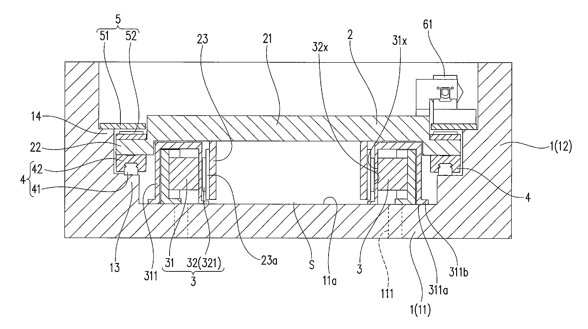
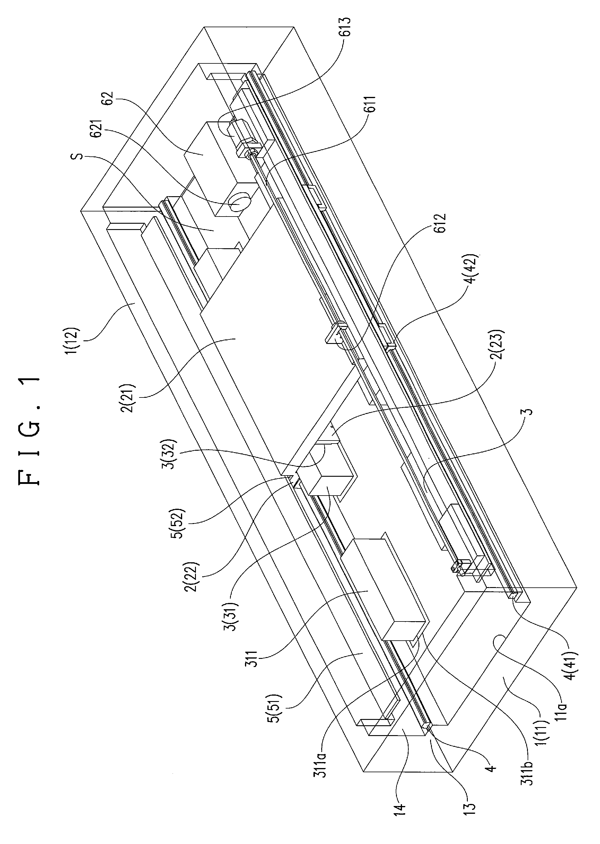
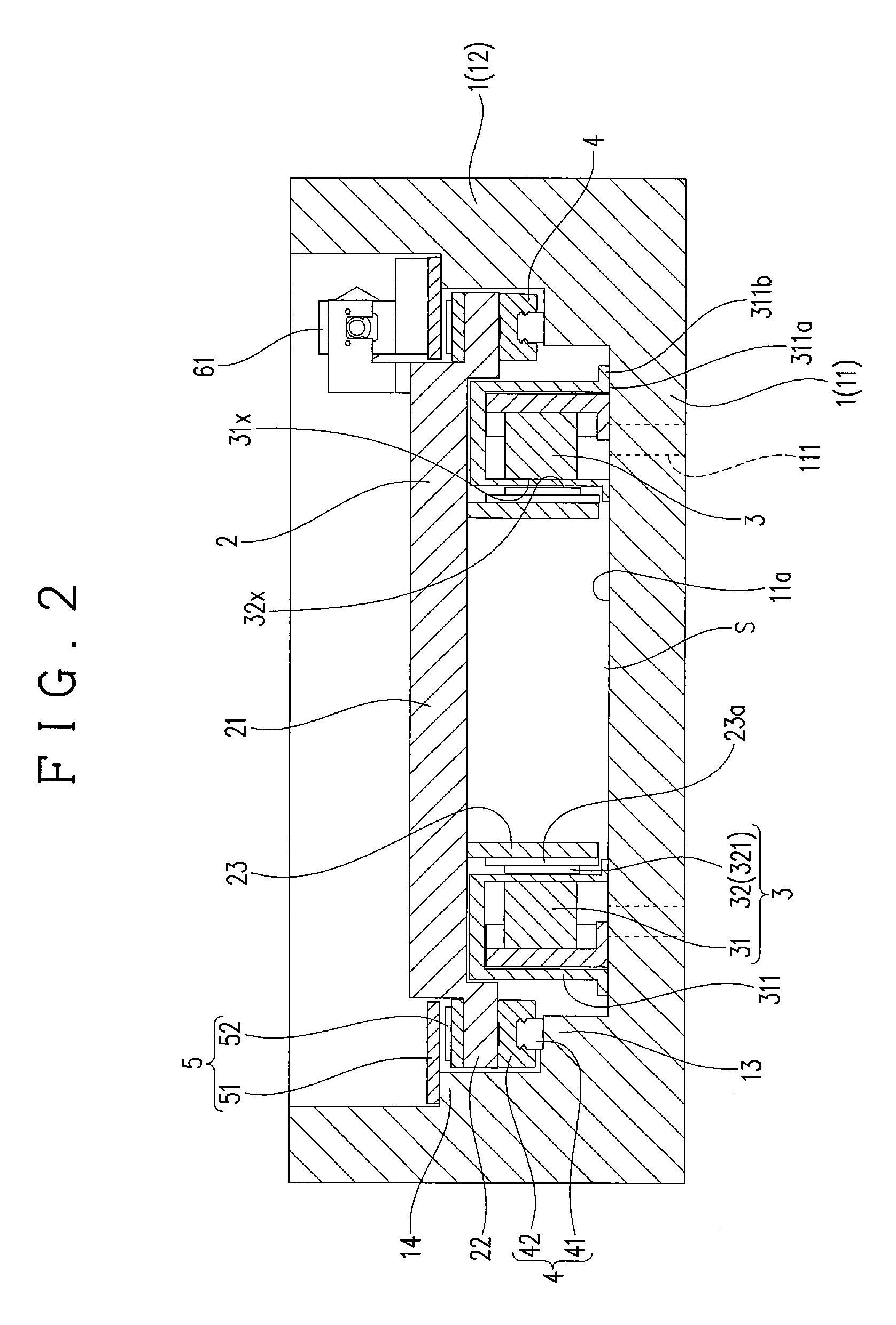
[0023]Hereinafter, the present invention is described by way of an embodiment with reference to the drawings. As for the directions, the following description is given under the assumption that the direction coincident with the longitudinal direction of a housing 1 is the longitudinal direction, and that the direction orthogonal to the longitudinal direction is the width direction. Note that the up, down, left, and right directions and the vertical and horizontal directions are based on the state of the present embodiment. However, for example, an embodiment, in which the upper and lower sides are reversed from the state of the present embodiment (that is, an embodiment in which an object is hung and conveyed), can also be implemented. Therefore, the present invention is not limited to the form in the directions of the present embodiment. Further, as for the inward and outward directions, the description is given under the assumption that the direction directed toward the center in ...


PUM


Abstract

A conveying apparatus includes: a housing; a movable member; a linear motor; and a cover. The linear motor includes a primary magnetic pole and a secondary magnetic pole each having a facing surface that faces the other and that is a plane along the longitudinal direction of the housing. The cover allows the primary magnetic pole to be located in an atmospheric environment, and the secondary magnetic pole to be located in a vacuum environment or a reduced pressure environment by separating the primary magnetic pole and the secondary magnetic pole from each other. The primary magnetic pole and the secondary magnetic pole face each other so that a direction of a magnetic attraction force generated therebetween and acting on their facing surfaces is different from directions of forces acting, due to an atmospheric pressure outside the housing, on the wall of the housing on which the cover is provided.

Description

CROSS-REFERENCE TO RELATED APPLICATION[0001]This application claims priority to Japanese Patent Application No. 2012-285897, the disclosure of which is incorporated herein by reference in its entirety.BACKGROUND OF THE INVENTION[0002]1. Field of the Invention[0003]The present invention relates to a conveying apparatus driven by a linear motor.[0004]2. Background Art[0005]A conveying apparatus driven by a linear motor is widely known. JP 2009-71955 A discloses an example of such a linear motor usable for the conveying apparatus. As shown in FIGS. 6A and 6B, a linear motor 100 includes primary magnetic poles 101 and secondary magnetic poles 102 arranged facing each other, and a cover 103 located between the magnetic poles 101 and 102. This cover 103 includes a mounting member 105 mounted on an inner wall 104 of a housing that constitutes the conveying apparatus, for example, as shown in FIG. 6B. The cover 103, for example, can allow the primary magnetic poles 101 on the fixed side to ...

Claims


Application Information

Patent Timeline
Patent Type & Authority Patents(United States)
IPC IPC(8): H02K41/02B65G54/02H02K5/128H02K41/03
CPCH02K5/128B65G54/02H02K41/031H02K41/03B60L13/03
Inventor MAEDA, MINORUMURAGUCHI, YOSUKEKOSAKI, MAMORUFUJIWARA, TAKASHI
Owner SINFONIA TECHNOLOGY CO LTD
Why Eureka
Try Eureka