Oil Separator

a technology of oil separator and separator plate, which is applied in the direction of lubricant mounting/connection, vortex flow apparatus, lighting and heating apparatus, etc., can solve the problem of limited oil separation function

Inactive Publication Date: 2012-02-16
SANDEN CORP
View PDF5 Cites 0 Cited by
  • Summary
  • Abstract
  • Description
  • Claims
  • Application Information

AI Technical Summary

Problems solved by technology

In a conventional oil separator, because the outer shape and the length dimension are large, the mounting position to an automobile has been limited, and further, because the structure is relatively complicated and the cost is high, it has not been so common to separate oil in refrigerant discharged from a

Method used


Image

  • Oil Separator
  • Oil Separator
  • Oil Separator

Examples


Embodiment Construction

[0039]Hereinafter, embodiments of the present invention will be explained referring to figures.

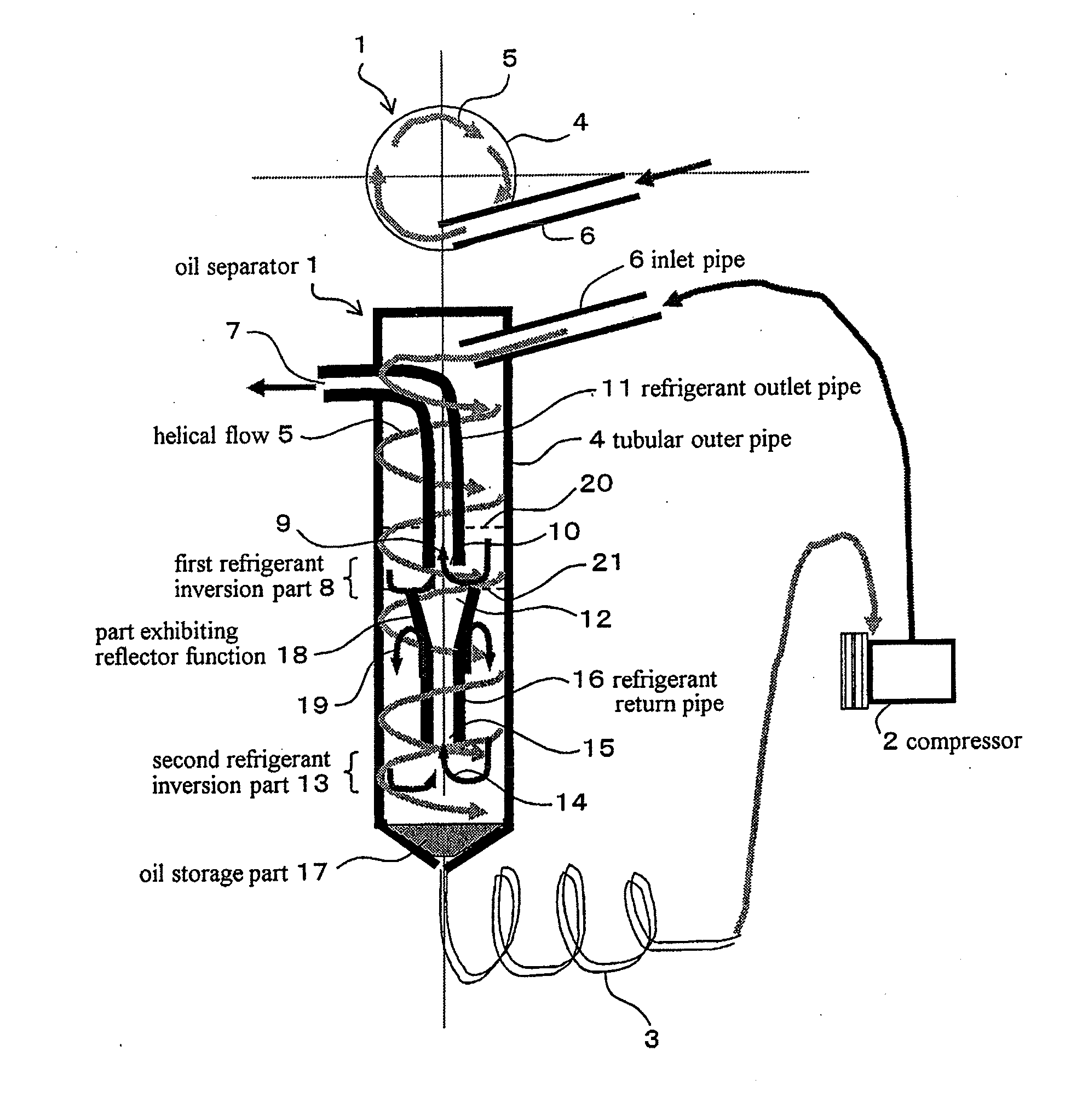
[0040]FIG. 1 shows schematic structure and operation of an oil separator according to an embodiment of the present invention. In the figure, symbol 1 indicates an oil separator, the oil separator 1 separates discharged refrigerant from a compressor 2 (high-temperature and high-pressure gas refrigerant), which contains refrigeration machine oil, into refrigeration machine oil and refrigerant, and returns the separated refrigerant to, for example, a condenser disposed at a downstream side in a refrigeration circuit, and returns the separated refrigeration machine oil into, for example, a crank case of compressor 2 through an oil return tube 3. Oil separator 1 has a tubular outer pipe 4 which is disposed on a outlet side of compressor 2 so as to extend in a vertical direction substantially at a constant diameter and at a configuration of a straight pipe, and an inlet pipe 6 provided at an upp...


PUM


Abstract

Provided is an oil separator which can separate refrigerant and refrigeration machine oil with high efficiency, which can effectively prevent the outflow of separated oil towards the refrigerant discharge path side, which can reduce pressure loss in the flow of refrigerant, and which can be made compact especially in the radial direction. The oil separator is provided with: a tubular outer pipe which is disposed on the compressor outlet side; an inlet pipe for introducing refrigerant containing refrigeration machine oil into the tubular outer pipe in such a manner as to produce a downward helical flow of refrigerant containing refrigeration machine oil along the inner surface of the tubular outer pipe; a refrigerant outlet pipe which has an external outflow port for the outflow of refrigerant to outside the tubular outer pipe, has a section extending in the axial direction of the tubular outer pipe at the central position of the tubular outer pipe, and allows the inflow, from the lower end of the above-mentioned section, of refrigerant separated from the refrigerant containing refrigeration machine oil having flowed down in the helical flow, and wherein the flow direction has been inverted in relation to the vertical direction at a first refrigerant inversion part; a refrigerant return pipe which extends in the axial direction of the tubular outer pipe at the central position of the tubular outer pipe, below the refrigerant outlet pipe, and which allows the inflow, from the lower end thereof, of refrigerant separated from the refrigerant containing refrigeration machine oil having flowed down in the helical flow, and wherein the flow direction has been inverted in relation to the vertical direction at a second refrigerant inversion part; and an oil storage part which is formed at the bottom of the tubular outer pipe. Furthermore, a part exhibiting a reflector function for preventing refrigeration machine oil stored in the oil storage part from flowing out into the refrigerant outlet pipe is provided between the refrigerant return pipe and the inner surface of the tubular outer pipe.

Description

TECHNICAL FIELD OF THE INVENTION[0001]The present invention relates to an oil separator which separates refrigeration machine oil mixed in refrigerant discharged from a compressor, and specifically, to an oil separator suitable to be disposed in a refrigeration circuit of an air conditioning system for a vehicle.BACKGROUND ART OF THE INVENTION[0002]For example, in a refrigeration circuit of an air conditioning system for a vehicle, there may be a case where provided is an oil separator having a function for separating refrigeration machine oil mixed in refrigerant discharged from a compressor and returning the separated refrigeration machine oil to the compressor. In a conventional oil separator, because the outer shape and the length dimension are large, the mounting position to an automobile has been limited, and further, because the structure is relatively complicated and the cost is high, it has not been so common to separate oil in refrigerant discharged from a compressor by an...

Claims


Application Information

Patent Timeline
IPC IPC(8): F25B43/02
CPCB04C5/103F25B43/02F25B2400/02
Inventor SAKANO, AKIRASATO, KENICHIRO
Owner SANDEN CORP
Why Eureka
Try Eureka