
Method for producing gaseous ammonium for ion-molecule-reaction mass spectrometry

a technology of ion-molecule reaction and ammonium, which is applied in the direction of particle separator tube details, electric discharge tube, particle separator tube, etc., can solve the problems of higher fragmentation, more complex mass spectra, and low selectivity, and achieve the effect of easy flow control of ions and/or neutrals and easy second ionization chambers

Active Publication Date: 2021-06-17
IONICON ANALYTIK GES
View PDF0 Cites 0 Cited by
  • Summary
  • Abstract
  • Description
  • Claims
  • Application Information

AI Technical Summary

Benefits of technology

The present invention provides an ion source with higher selectivity and simpler spectra compared to previous methods involving NHCL or NH4+. The invention involves using a mixture of N2 and H2O in a first area of the ion source and then applying at least one field or adjusting pressure conditions in a second area to promote flow of ions and induce collisions and reactions with neutral H2O and N2, resulting in a high yield of NH4+ with almost no other ions. The use of NH3 is avoided, reducing the negative side effects caused by this dangerous, toxic and corrosive source gas. The ion source has a preferred embodiment with two areas, which allows for easier flow control and adjustment of pressure without affecting the other area.

Problems solved by technology

Due to the large number of disadvantages associated with the generation of NH4+, this ion is rarely used in IMR-MS devices as reagent ion.
H3O+ is still the standard reagent ion despite its disadvantages such as lower selectivity, more complex mass spectra and higher levels of fragmentation.
Absolutely no NH3 needs to be added to this process at any stage, which is in stark contrast to the prior art, and therefore the negative side effects caused by the use of this dangerous, toxic and corrosive source gas in previous designs are diminished.

Method used


Image

  • Method for producing gaseous ammonium for ion-molecule-reaction mass spectrometry
  • Method for producing gaseous ammonium for ion-molecule-reaction mass spectrometry

Examples


Embodiment Construction

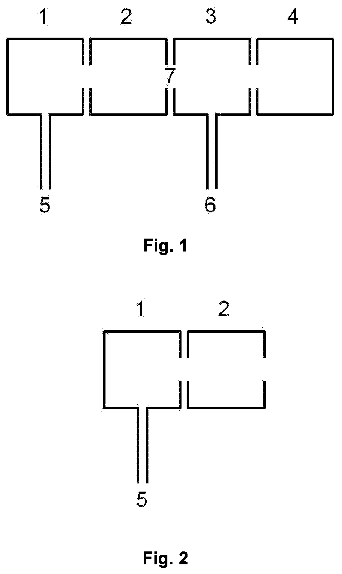
lass="d_n">[0063]FIG. 1 is a schematic view of a typical IMR-MS instrument, comprising a first ionization chamber 1, a second ionization chamber 2, a reaction region 3 (e.g. drift, flow or flow-drift tube in PTR-, SIFT- and SIFDT-MS, respectively), a mass spectrometer region 4 (e.g. TOF, multipole, ion trap, MSn, etc.), one or more inlet(s) 5 for source gases, one or more inlet(s) 6 for sample and, if needed, carrier or buffer gas, region 7 between 2 and 3.

[0064]FIG. 2 shows a schematic view of the parts needed for the present invention: first ionization chamber 1, second ionization chamber 2, one or more inlet(s) 5 for source gases.

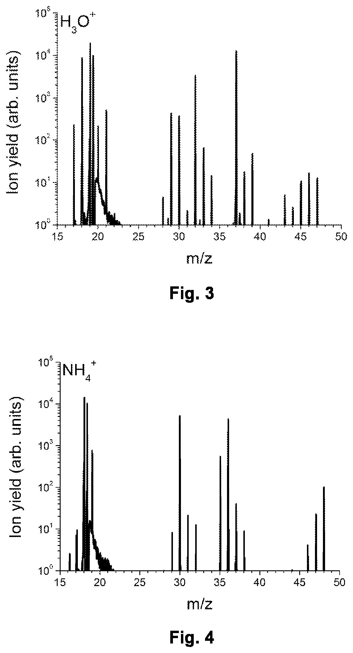
[0065]FIG. 3 shows a part of a mass spectrum obtained with the instrument running in H3O+ mode.

[0066]FIG. 4 shows a part of a mass spectrum obtained with the instrument running in NH4+ mode, i.e. in the mode according to the invention.

[0067]The present invention solves all of the above-mentioned problems associated with the use of NH3 source gas and enab...


PUM


Abstract

Method for obtaining gaseous ammonium (NH4+) from an ion source, the ion source comprising a first area (1) and a second area (2) in a fluidly conductive connection, comprising the steps of a) introducing N2 and H2O into the first area (1) and second area (2) of the ion source; b) applying an ionization method to the mixture of N2 and H2O in the first area (1); c) applying at least one electric field or adjusting pressure conditions or a combination of applying at least one electric field and adjusting pressure conditions promoting flow of ions from the first area (1) to the second area (2) and inducing reactions of the ions in the second area (2); d) conducting NH4+ out of the ion source. Ion Molecule Reaction-Mass Spectrometry instrument implementing this method for producing NH4+ and then conducting NH4+ to the reaction region.

Description

[0001]The present invention relates to a method for obtaining gaseous ammonium (NH4+) from an ion source. The invention also relates to a method for ionizing a sample with gaseous ammonium, comprising obtaining ammonium and ionizing the sample in a reaction chamber. Furthermore, the invention relates to a method of detecting the ion yield of the mass-to-charge ratio of ions by detecting the ions in an MS-instrument. Finally, the invention relates to an IMR-MS instrument, comprising an ion source; a reaction region connected to said ion source; a mass spectrometer region connected to said reaction region; at least one inlet for source gases; at least one inlet for a sample into the reaction region; an N2-source; a H2O source; and at least one pump.BACKGROUND OF THE INVENTION[0002]Gas analysis with Ion-Molecule-Reaction-Mass Spectrometry (IMR-MS) has been well established for many decades (see e.g. A. M. Ellis, C. A. Mayhew. Proton Transfer Reaction Mass Spectrometry Principles and Ap...

Claims


Application Information

Patent Timeline
IPC IPC(8): H01J49/14H01J49/04
CPCH01J49/145H01J49/0422
Inventor HARTUNGEN, EUGEN
Owner IONICON ANALYTIK GES
Learn More