
Magnetic valve assembly

Inactive Publication Date: 2016-10-13
CORRELATED MAGNETICS RES LLC
View PDF0 Cites 0 Cited by
  • Summary
  • Abstract
  • Description
  • Claims
  • Application Information

AI Technical Summary

Benefits of technology

The invention is a valve mechanism that allows for the mixing of hot and cold water. The valve has a structure that minimizes leakage of the water outside of the valve. The movement of the valve parts controls the flow and mixing of the hot and cold water. The valve also has a handle that can be moved in different directions. The technical effect of this invention is a more efficient and accurate control of the mixing of hot and cold water in a valve mechanism.

Problems solved by technology

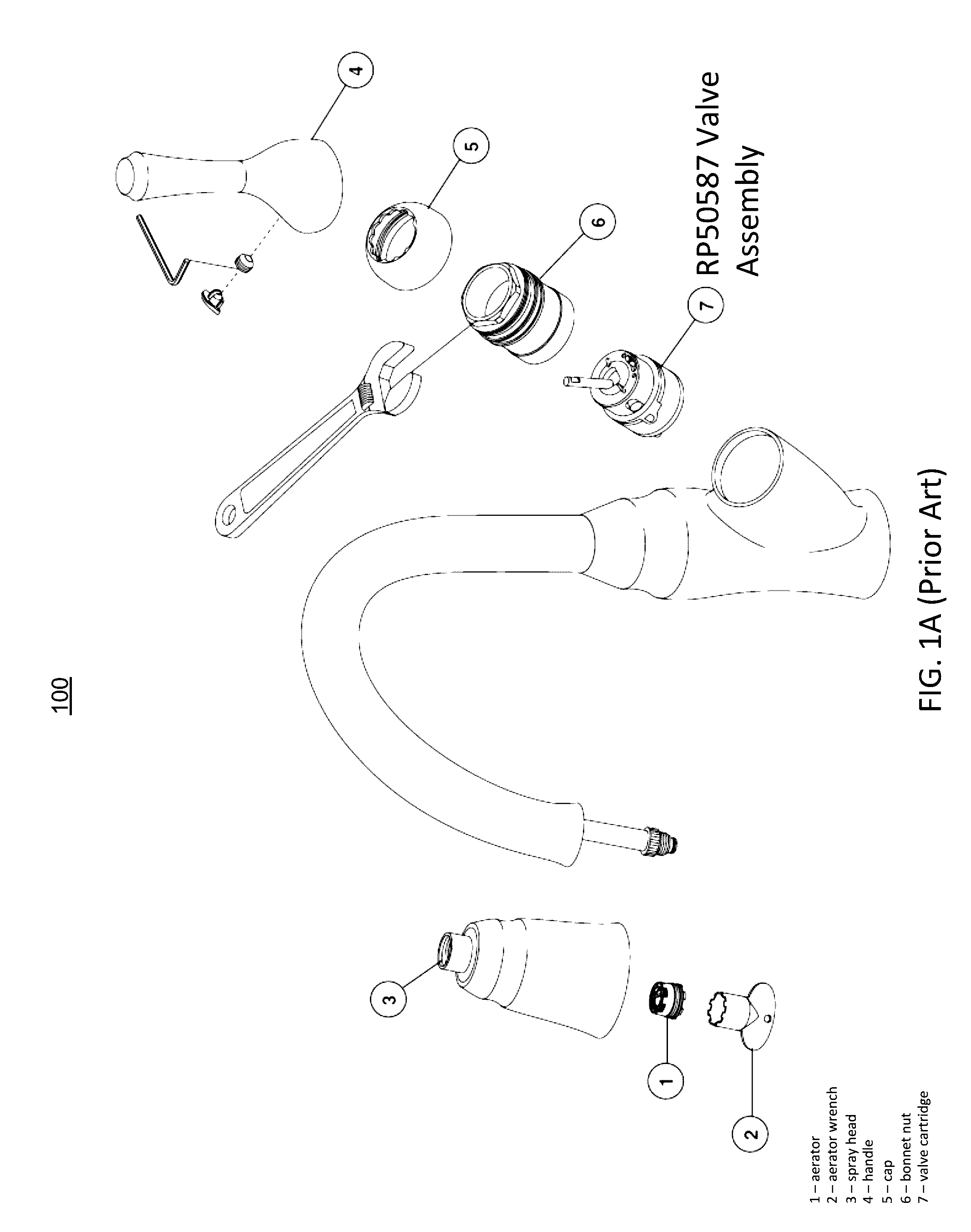
As explained above, modern disc-based valve assemblies typically involve discs having precisely polished surfaces that provide a longer lasting seal, where the disc polishing process can be quite expensive.
But, such assemblies can eventually develop leaks between the discs after extended periods of operation, which can result in substantial property damage and thus there remains a liability concern of faucet leakage.

Method used


Image

  • Magnetic valve assembly
  • Magnetic valve assembly
  • Magnetic valve assembly

Examples


Embodiment Construction

[0054]Certain described embodiments of the invention described herein may relate by way of example, but not limitation, to systems and / or apparatuses comprising magnetic structures, magnetic and non-magnetic materials, methods for using magnetic structures, magnetic structures produced via magnetic printing, magnetic structures comprising arrays of discrete magnetic elements, combinations thereof, and so forth. Example realizations for such embodiments may be facilitated, at least in part, by the use of an emerging, revolutionary technology that may be termed correlated magnetics. This revolutionary technology referred to herein as correlated magnetics was first fully described and enabled in the co-assigned U.S. Pat. No. 7,800,471 issued on Sep. 21, 2010, and entitled “A Field Emission System and Method”. The contents of this document are hereby incorporated herein by reference. A second generation of a correlated magnetic technology is described and enabled in the co-assigned U.S....


PUM

PropertyMeasurementUnit
Magnetic structureaaaaaaaaaa
Flow rateaaaaaaaaaa
Magnetismaaaaaaaaaa

Abstract

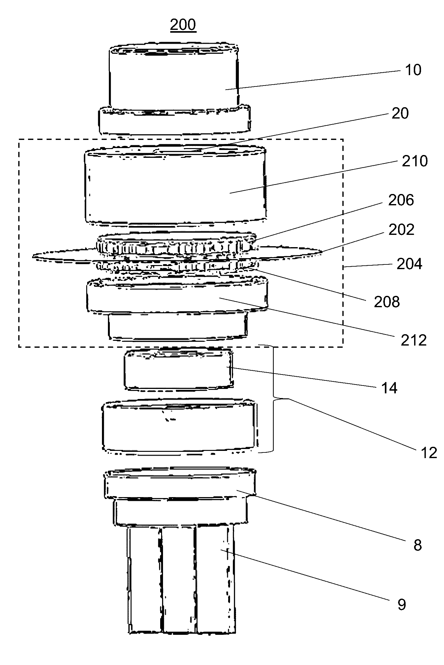
A valve assembly comprises a sealed container connected to a hot water supply line and a cold water supply line. The sealed container has an outlet for supplying at least one of hot water or cold water to a faucet. A valve mechanism is located inside the sealed container comprising a stationary mixing part and a moveable mixing part. A magnetic coupling adapter has a first magnetic structure located outside of a wall of the sealed container. A first magnetic structure is made of a first magnetizable material having a first plurality of first printed maxels having a first polarity pattern. A second magnetic structure located inside the wall of the sealed container is made of a second magnetizable material having a second plurality of second printed maxels having a second polarity pattern that is complementary to the first polarity pattern. The first magnetic structure and second magnetic structure are magnetically coupled across the wall of the sealed container. A first adapter interface component located outside of the wall of the sealed container is associated with the first magnetic structure. A second adapter interface component located inside the wall of the sealed container is associated with the second magnetic structure and the moveable mixing part. A movement control mechanism includes a moveable handle associated with the first adapter interface, which is configured to control a movement of the magnetic coupling adapter and thereby a movement of the moveable mixing part to control flow and mixing of the hot and cold water.

Description

RELATED APPLICATIONS[0001]This application is a continuation of non-provisional application Ser. No. 14 / 472,945 titled “Magnetic Valve Assembly” filed Aug. 29, 2014 by Fullerton et al., which claims the benefit under 35 USC 119(e) of provisional application 61 / 871,689, titled “Magnetic Valve Assembly”, filed Aug. 29, 2013 by Fullerton et al.[0002]Non-provisional application Ser. No. 14 / 472,945 is a continuation-in-part of non-provisional application Ser. No. 14 / 198,226, titled “Correlated Magnetic System and Method”, filed Mar. 5, 2014 by Fullerton et al., which claims the benefit under 35 USC 119(e) of provisional application 61 / 794,427, titled “Method for Correcting Bias in Correlated Field Emission Structures”, filed Mar. 15, 2013 by Fullerton et al., provisional application 61 / 798,233, titled “Method for Using Symbols in Coded Field Emission Structures”, filed Mar. 15, 2013 by Roberts et al., provisional application 61 / 798,453, titled “Apparatus and Method for Mechanical Augment...

Claims


Application Information

Patent Timeline
IPC IPC(8): F16K31/08E03C1/04H01F7/02F16K11/14
CPCF16K31/088F16K11/14E03C2001/026H01F7/021E03C1/0412F16K11/0782B23P15/001E04F13/0883
Inventor FULLERTON, LARRY W.ROBERTS, MARK D.
Owner CORRELATED MAGNETICS RES LLC
Learn More