Sliding element for adjustable jewelry

a sliding element and adjustable technology, applied in the field of jewelry, can solve the problems of not providing a suitable surface area, complicated manufacturing of conventional sliding elements, etc., and achieve the effect of reducing the sliding resistance of the band

Active Publication Date: 2016-04-05
ALEX AND ANI
View PDF12 Cites 32 Cited by
  • Summary
  • Abstract
  • Description
  • Claims
  • Application Information

AI Technical Summary

Benefits of technology

[0011]The sliding flange can include a coating disposed on a surface thereof. The coating can include teflon or any other suitable coating for reducing the sliding resistance of the band.

Problems solved by technology

Conventional sliding elements can be complicated to manufacture and install on bands and also do not provide suitable surface area for indicia to be applied thereto.

Method used


Image

  • Sliding element for adjustable jewelry
  • Sliding element for adjustable jewelry

Examples


Embodiment Construction

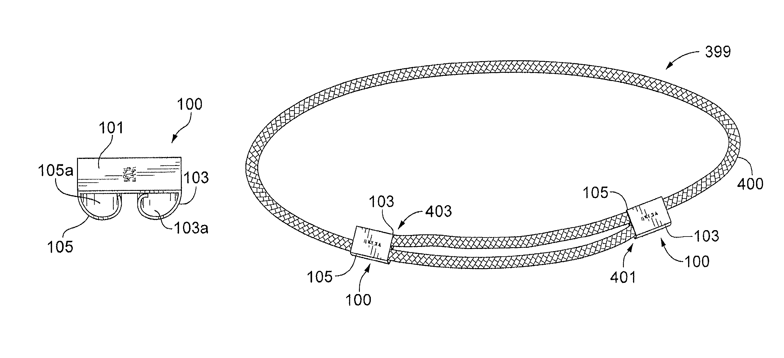
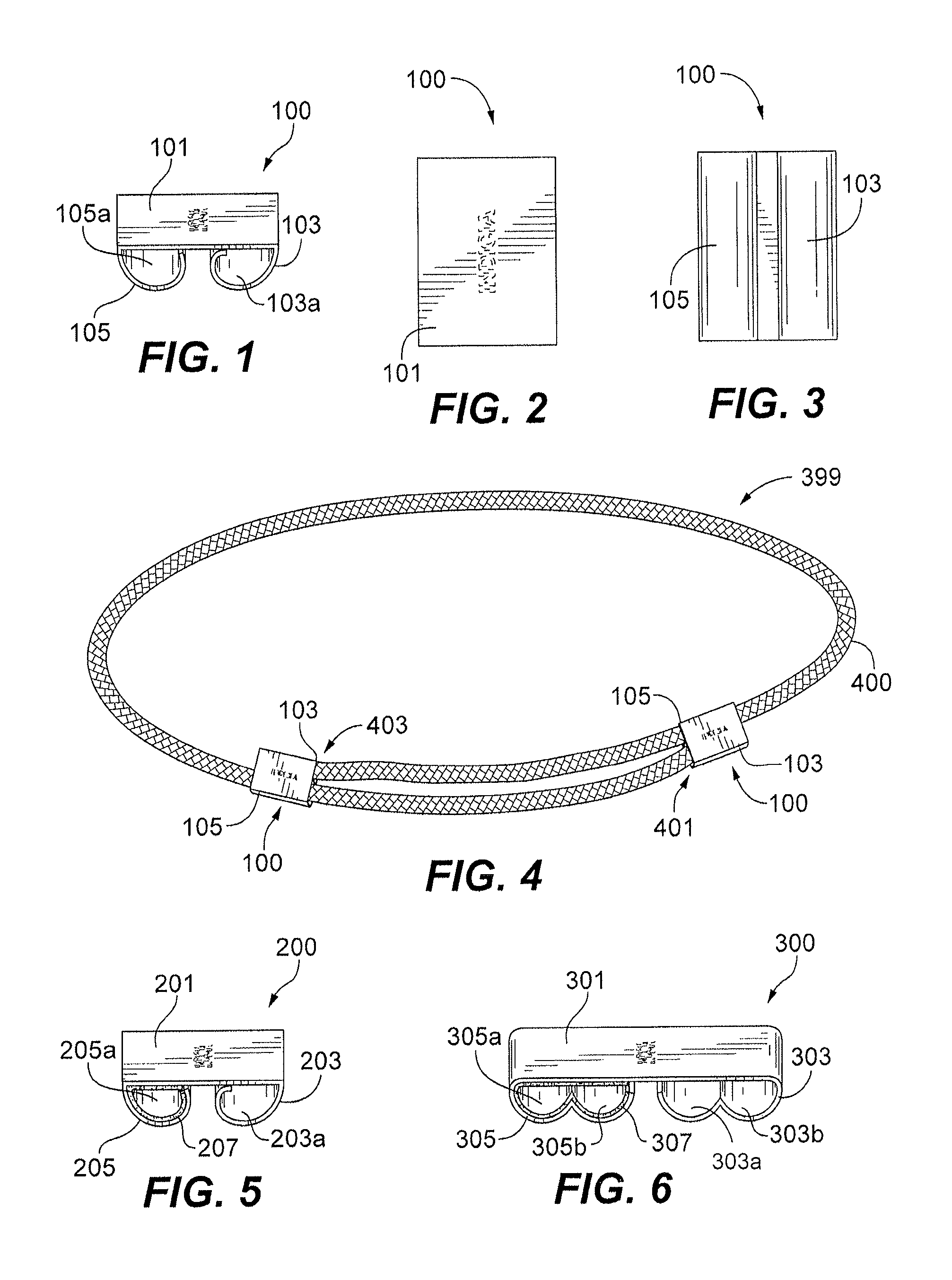
[0026]Embodiments of this disclosure are now described more fully with reference to the accompanying drawings, in which an illustrated embodiment is shown. This disclosure is not limited in any way to the illustrated embodiment as the illustrated embodiment described below is merely an example which can be embodied in various forms, as appreciated by one skilled in the art. Therefore, it is to be understood that any structural and functional details disclosed herein are not to be interpreted as limiting, but merely as a basis for the claims and as a representative for teaching one skilled in the art to variously employ the embodiments disclosed herein. Furthermore, the terms and phrases used herein are not intended to be limiting but rather to provide an understandable description of the embodiments herein.

[0027]The present disclosure generally relates to articles of jewelry and sliding elements therefor. Turning now descriptively to the drawings, in which similar reference numerals...


PUM

PropertyMeasurementUnit
axial dimensionaaaaaaaaaa
dimensionaaaaaaaaaa
lengthsaaaaaaaaaa

Abstract

Disclosed is a sliding element for use with jewelry including a plate body, a sliding flange extending from a first lateral edge of the plate body, and a crimping flange extending from a second lateral edge of the plate body. The plate body, the sliding flange, and the crimping flange can be stamped from a uniform flat metal sheet.

Description

BACKGROUND OF THE INVENTION[0001]1. Field of the Invention[0002]The invention generally relates to jewelry and more particularly to slider elements for jewelry.[0003]2. Background of the Related Art[0004]Sliding elements (e.g., beads) have been used to create adjustable jewelry such as bracelets and necklaces. Traditionally, the sliding element includes a cast or formed shape. The ends of a band can be affixed to a portion of the sliding element using adhesives, welding, or the like while other portions of the band can pass through a sliding portion of sliding element to allow adjustment of the size of the bands. For example, see U.S. Design Pat. No. D703,088 which discloses an adjustable bracelet.[0005]Conventional sliding elements can be complicated to manufacture and install on bands and also do not provide suitable surface area for indicia to be applied thereto. Improved sliding elements for jewelry bands that reduce manufacturing cost and require simplified installation onto ba...

Claims


Application Information

Patent Timeline
Patent Type & Authority Patents(United States)
IPC IPC(8): A44C5/22A44C5/00B21D13/10
CPCA44C5/22A44C5/0069B21D13/10Y10T24/3987A44B11/04A44C15/005A44B11/06A44C5/18A44C5/185A44C15/00
Inventor RAFAELIAN, CAROLYN A.
Owner ALEX AND ANI
Why Eureka
Try Eureka