

Drive control apparatus for controlling drive of inductive load and drive control method for controlling the same
- Summary
- Abstract
- Description
- Claims
- Application Information
AI Technical Summary
Benefits of technology
Problems solved by technology
Method used
Image

Examples
first embodiment
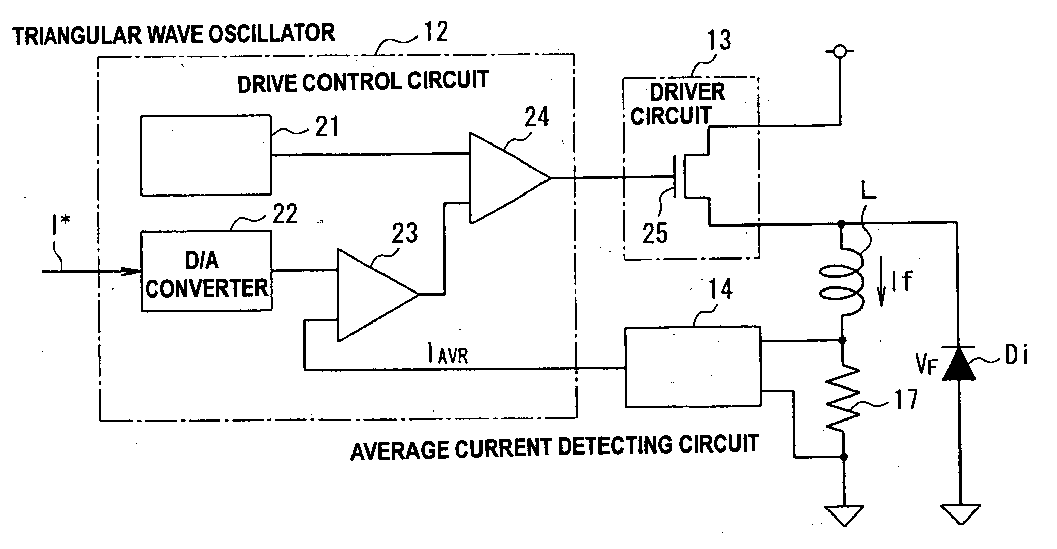
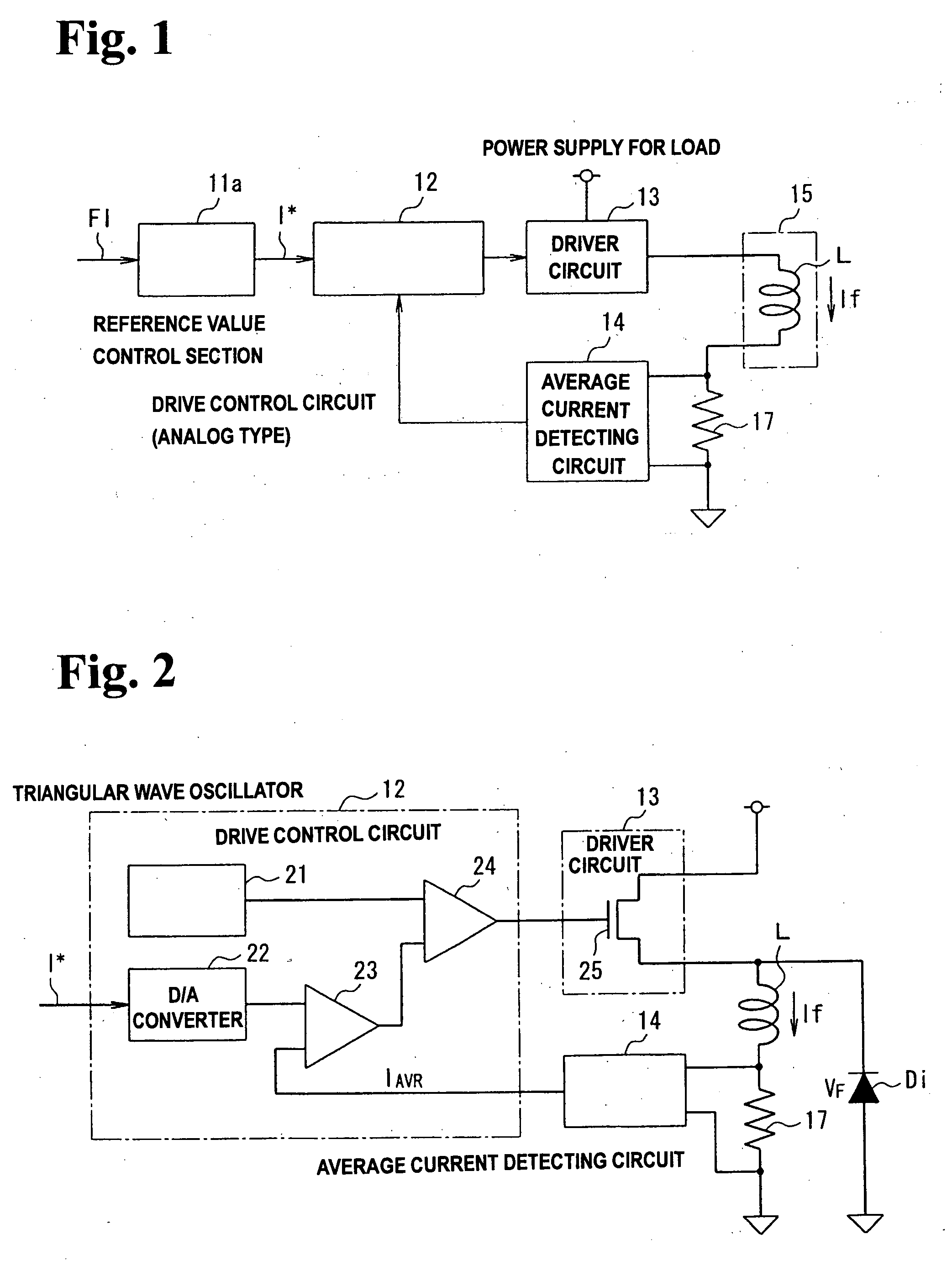
[0070]FIG. 1 is a block diagram briefly describing a closed loop control system, to which a drive control apparatus according to the invention for controlling the drive of an inductive load is applied.
[0071]In FIG. 1, driver circuit 13 is connected to the first end of inductive load 15. Current detecting resistor 17 is connected in series to the second end of inductive load 15. Drive control circuit 12 that conducts a PWM control by analog data processing is disposed in the front stage of driver circuit 13. Reference value control section 11a is disposed in the front stage of drive control circuit 12.
[0072]Average current detecting circuit 14 is connected between the first and second ends of current detecting resistor 17. The output from average current detecting circuit 14 is connected to drive control circuit 12.
[0073]For controlling the drive of inductive load 15, drive control circuit 12 changes current If flowing through inductive load 15 by the PWM control so that current If f...
second embodiment
[0108]FIG. 13 is a block diagram briefly describing a closed loop control system, to which a drive control apparatus according to the invention for controlling the drive of an inductive load is applied.
[0109]In FIG. 13, reference value control section 11b is disposed according to the second embodiment in substitution for reference value control section 11a in FIG. 1. In FIG. 1, the set current value data FI is fed to reference value control section 11a as a variable. In contrast, the set current value data FI and a current ripple waveform control data FR are fed to reference value control section 11b as variables in FIG. 13. The current ripple waveform control data FR specifies the current ripple amount of the reference current value I*.
[0110]FIG. 14 is a block diagram briefly describing the structure of reference value control section 11b shown in FIG. 13.
[0111]In FIG. 14, reference value control section 11b includes period and time data storage section 31b, current ripple data sto...
third embodiment
[0113]FIG. 15 is a block diagram briefly describing the structure of reference value control section 11c according to the invention.
[0114]In FIG. 15, reference value control section 11c according to the third embodiment includes period and time data storage section 31c, current ripple data storage section 32c, set current data storage section 33c, timing generator circuit 34c, and signal generator circuit 35c. Period and time data storage section 31c stores the waveform control data FR1 of the reference current value I* as a variable. Current ripple data storage section 32c stores the current ripple data FR2 of the reference current value I* as a variable. Set current data storage section 33c stores the set current value data FI as a variable. Timing generator circuit 34c generates the generation timing for generating the reference current value I*. Signal generator circuit 35c generates the waveform of the reference current value I*. The waveform control data FR1 specifies the peri...
PUM
 Abstract
Description
Claims
Application Information