Timepiece wheel train and timepiece

a technology of timepieces and wheels, applied in the field of timepiece wheel trains, can solve the problems that dlc powder can continue to reduce sliding resistance, and achieve the effect of reducing sliding resistan

Active Publication Date: 2012-05-01
SEIKO EPSON CORP
View PDF7 Cites 9 Cited by
  • Summary
  • Abstract
  • Description
  • Claims
  • Application Information

AI Technical Summary

Benefits of technology

[0008]A timepiece and a timepiece wheel train according to the present invention can effectively reduce sliding resistance between a shaft unit and a bearing unit.

Problems solved by technology

Furthermore, by using lubricating oil, wear particles that are produced do not accumulate in other parts of the wheel train, and the DLC powder can continue to reduce sliding resistance.

Method used


Image

  • Timepiece wheel train and timepiece
  • Timepiece wheel train and timepiece
  • Timepiece wheel train and timepiece

Examples


Embodiment Construction

[0054]A preferred embodiment of the present invention is described below with reference to the accompanying figures.

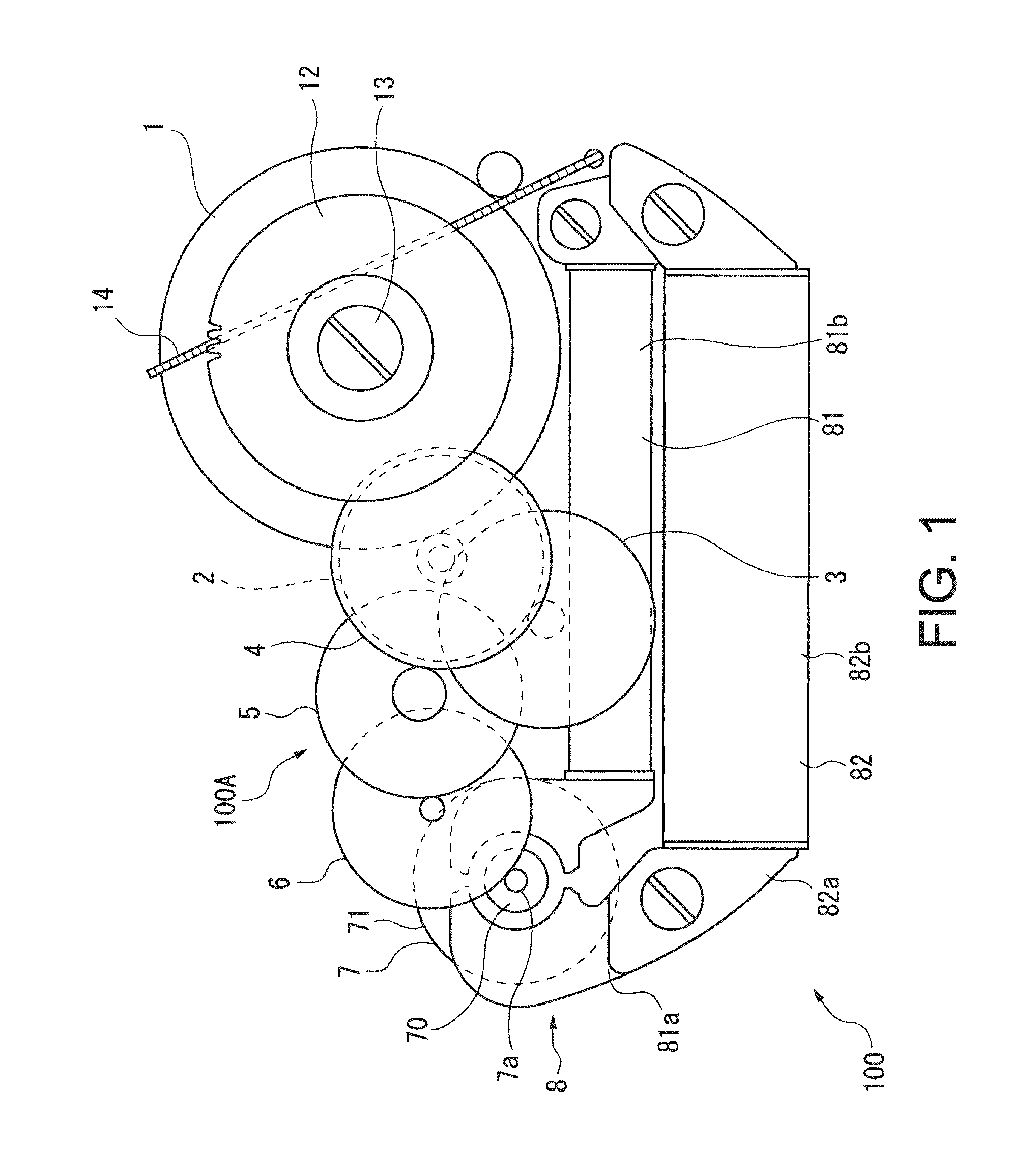
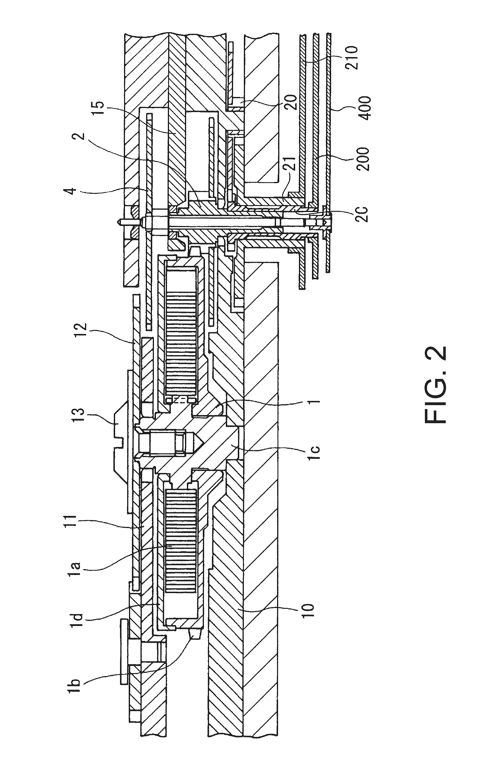
[0055]FIG. 1 is a plan view showing some of the main parts of an electronically controlled mechanical timepiece (timepiece) having a timepiece wheel train according to the invention, and FIG. 2 and FIG. 3 are section views of the timepiece shown in FIG. 1.

[0056]The electronically controlled mechanical timepiece 100 (referred to as simply a timepiece below) according to this embodiment of the invention has a movement barrel 1 including a mainspring 1a as a mechanical energy source, a barrel wheel 1b, a barrel arbor 1c, and a barrel cover 1d. The outside end of the mainspring 1a is attached to the barrel wheel 1b, and the inside end is attached to the barrel arbor 1c. The barrel arbor 1c is supported by the main plate 10 and train wheel bridge 11, and is fastened by a ratchet wheel screw 13 to rotate in unison with a ratchet wheel 12.

[0057]The ratchet wheel 12 is engaged...


PUM


Abstract

A timepiece wheel train includes a rotating body with a shaft unit, a bearing unit that rotatably supports the shaft unit of the rotating body, and a lubricating oil in which powder from a diamond-like carbon film is dispersed disposed between the shaft unit and the bearing unit.

Description

CROSS-REFERENCE TO RELATED APPLICATIONS[0001]Japanese Patent application Nos. 2009-091844, 2010-014306 and 2010-046440 are each incorporated by reference herein in its entirety.BACKGROUND[0002]1. Field of Invention[0003]The present invention relates to a timepiece wheel train for driving the hands of a timepiece, and to a timepiece having this timepiece wheel train.[0004]2. Description of Related Art[0005]Wear between shaft parts and bearing units normally occurs in a timepiece wheel train that drives the hands of a timepiece due to the high side pressure applied to the shaft parts of each wheel, and this wear can lead to a variety of problems, including increased drive resistance caused by wear particles produced by this wear and deterioration of the lubricating oil, a shorter timepiece service life, and a loss of precision in the timepiece movement. Addressing this issue, Japanese Unexamined Patent Appl. Pub. JP-A-H11-133162 teaches a configuration that lowers wear between sliding...

Claims


Application Information

Patent Timeline
Patent Type & Authority Patents(United States)
IPC IPC(8): G04B19/02G04B29/00
CPCC10M125/02G04B31/08G04B31/004G04B31/06C10M2201/041C10N2240/06C10N2040/06
Inventor TAKEUCHI, MASAOMURAI, MASAMISEKI, SHIGEAKIYOSHIDA, TOMOKAZU
Owner SEIKO EPSON CORP
Why Eureka
Try Eureka