System for automatic lubrication

a technology of automatic lubrication and system, which is applied in the direction of engine lubrication, water supply installation, gas/liquid distribution and storage, etc. it can solve the problems of slow venting time, low cost version of this system does not provide individual adjustment of each output, and the frequency of grease application, so as to prevent inadvertent rotation of the piston during use

Active Publication Date: 2016-04-05
IFIELD ENG
View PDF24 Cites 5 Cited by
  • Summary
  • Abstract
  • Description
  • Claims
  • Application Information

AI Technical Summary

Benefits of technology

[0022]Preferably, the system includes a one-way valve at the injector end of the feed conduit arranged to prevent lubricant returning to the injector when the pump is inactive.
[0049]In a further aspect, the invention provides a valve for use as a blocked-line vent valve in an automatic lubrication system, the valve comprising a body, a valve poppet and a spring, the body comprising an inlet port adapted to connect to the feed line in use and an outlet port open to atmosphere in use, the valve poppet arranged to move axially within the body with a first valve seat formed at a first end of the valve poppet, a second valve seat formed within the body, the spring urging the first valve seat against the second valve seat so that the pressure setting of the valve is a function of the force of the spring and the area enclosed by a seat diameter, formed by the contact of the first and second valve seats, wherein an outer diameter of the poppet is many times larger than that of the seat diameter and engages with sliding contact with the body, providing a partial seal, arranged that discharge of lubricant past the seat diameter will then act on the outer diameter, reducing the pressure setting of the valve.
[0056]Preferably, the piston seal is arranged to have a flexible lip configured to permit free flow of lubricant from the inlet to the outlet, but acts to prevent flow in the reverse direction.
[0059]Preferably, inadvertent rotation of the piston during use is prevented by friction means between the piston and the spring sleeve.

Problems solved by technology

This system can have disadvantage with longer supply lines between the pump and injectors in that the viscosity of the grease can lead to slow venting times so that the maximum frequency of grease application has to be reduced to ensure that the injectors reset.
Lower cost versions of this system do not provide individual adjustment of each output.
They are sensitive to particulate contamination, and a stoppage of one output also causes all the others in the same bank to stop as well.
Operation of a lubrication system is only useful when it is functioning correctly.
If it is the case that the operator can use the machine and continue to operate unknowingly with a faulty system then there is the possibility that the automatic system is less certain than using a manual grease gun for each point.
The most vulnerable part of the system in many machines is the feed line from the injector to the bearing, as this is often not easily accessible, adjacent to moving parts, and subject to misadventure, such as rocks falling out of a loader bucket.
There are some systems that apply sensors to the lubrication point using wires within the feed lines connecting back to a monitoring computer, but these are expensive and complex, and the majority of installations trust to luck and frequent inspections, and accept the occasional bearing failure caused by a lubrication system shortcoming as a reality of operation.

Method used


Image

  • System for automatic lubrication
  • System for automatic lubrication
  • System for automatic lubrication

Examples


Embodiment Construction

[0080]This section describes a preferred embodiment of the complete implementation of the invention as a lubrication system. Some performance benefit can be gained by use of some of the components of the invention, as is discussed in later sections.

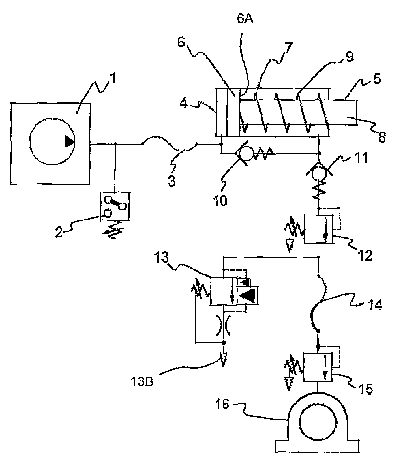
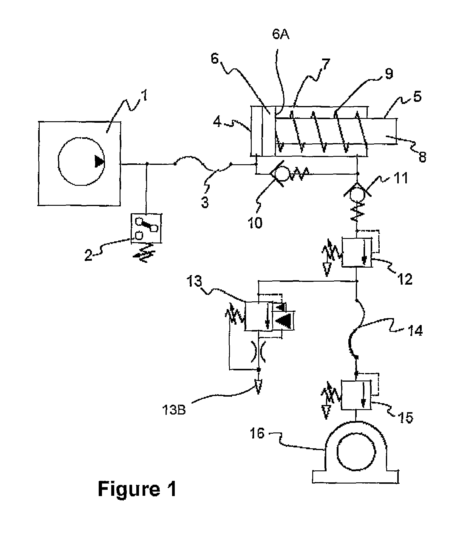
[0081]FIG. 1 shows a schematic diagram of the system. 1 is a conventional grease pump assemblage as suitable for a single line lubrication system, consisting of known means to periodically supply grease under pressure for a set period and then vent the pressure back to its reservoir. A pressure sensor 2 is provided, typically a simple pressure switch, that is set to operate at a pressure slightly lower than the maximum pressure of the grease pump, so that it normally activates for a period of time in each lubrication cycle.

[0082]Connecting line 3 indicates that there can be a significant length of supply line between the pump and intensifying injector 4. Only one injector is shown in FIG. 1 but an automatic lubrication system will normall...


PUM


Abstract

A system for automatically delivering lubricant to at least one bearing (16) has a lubricant pump (1) feeding lubricant under pressure through a supply line (3) to an injector (4). The injector, driven by the lubricant, sends a measured amount of lubricant down feed line (14) to bearing (16). A pressurizing valve (15) maintains injection pressure in the feed line (14) enabling any failure of supply to be detected as a pressure drop at pressure switch (2). Preferred features include the incorporation of a second pressurizing valve (12) at the injector end of the feed line (14), a blocked-line vent valve (13) to enable detection of a blocked or crushed feed line, and check valves (10) and (11). The injector (4) is preferably configured to produce a higher pressure at the outlet than the inlet, and various versions of this intensifying injector are described and claimed.

Description

FIELD OF THE INVENTION[0001]This invention relates to a system and apparatus for automatic lubrication of the bearings used on mechanical equipment, replacing manual greasing to improve reliability and reduce operational costs, and has been devised particularly though not solely for use on machinery operating in arduous conditions such as used in mining or earth moving.BACKGROUND OF THE INVENTION[0002]Automatic lubrication systems are used on many types of machinery, from large fixed plant to smaller mobile construction and mining equipment. In general they replace previous procedures requiring manual application using grease guns and the like. There is a wide range of equipment available in the market, performing a useful service in improving machine reliability, reducing the hazards of manual access to the machine, reducing the time requirement for maintenance and minimising the quantity of lubricant required.[0003]A typical automatic lubrication system includes a pumping system t...

Claims


Application Information

Patent Timeline
Patent Type & Authority Patents(United States)
IPC IPC(8): F16N7/38F16N27/00
CPCF16N27/00F16N7/385F16N2210/14Y10T137/0318Y10T137/85978
Inventor IFIELD, BENJAMINIFIELD, ROBERT WILLIAMIFIELD, CRAIG ALAN
Owner IFIELD ENG
Why Eureka
Try Eureka