Gas-liquid separator and inkjet recording apparatus using the same

a technology of inkjet recording apparatus and separator, which is applied in the direction of liquid degasification, separation processes, printing, etc., can solve the problems of deterioration in the running cost of the inkjet recording apparatus of the customer, and achieve the effects of reducing solvent consumption, compact structure, and free set-up directivity

Active Publication Date: 2016-04-12
HITACHI IND EQUIP SYST CO LTD
View PDF18 Cites 2 Cited by
  • Summary
  • Abstract
  • Description
  • Claims
  • Application Information

AI Technical Summary

Benefits of technology

[0008]The present invention provides the gas-liquid separator that has a compact structure and free set-up directivity, and further provides the inkjet recording apparatus capable of reducing the solvent consumption.

Problems solved by technology

This may lead to deterioration in the running cost of the inkjet recording apparatus of the customer.
The gas-liquid separator disclosed in JP-A-2003-4343 has a problem of failing to perform the gas-liquid separation upon change in its set-up direction.

Method used


Image

  • Gas-liquid separator and inkjet recording apparatus using the same
  • Gas-liquid separator and inkjet recording apparatus using the same
  • Gas-liquid separator and inkjet recording apparatus using the same

Examples


first example

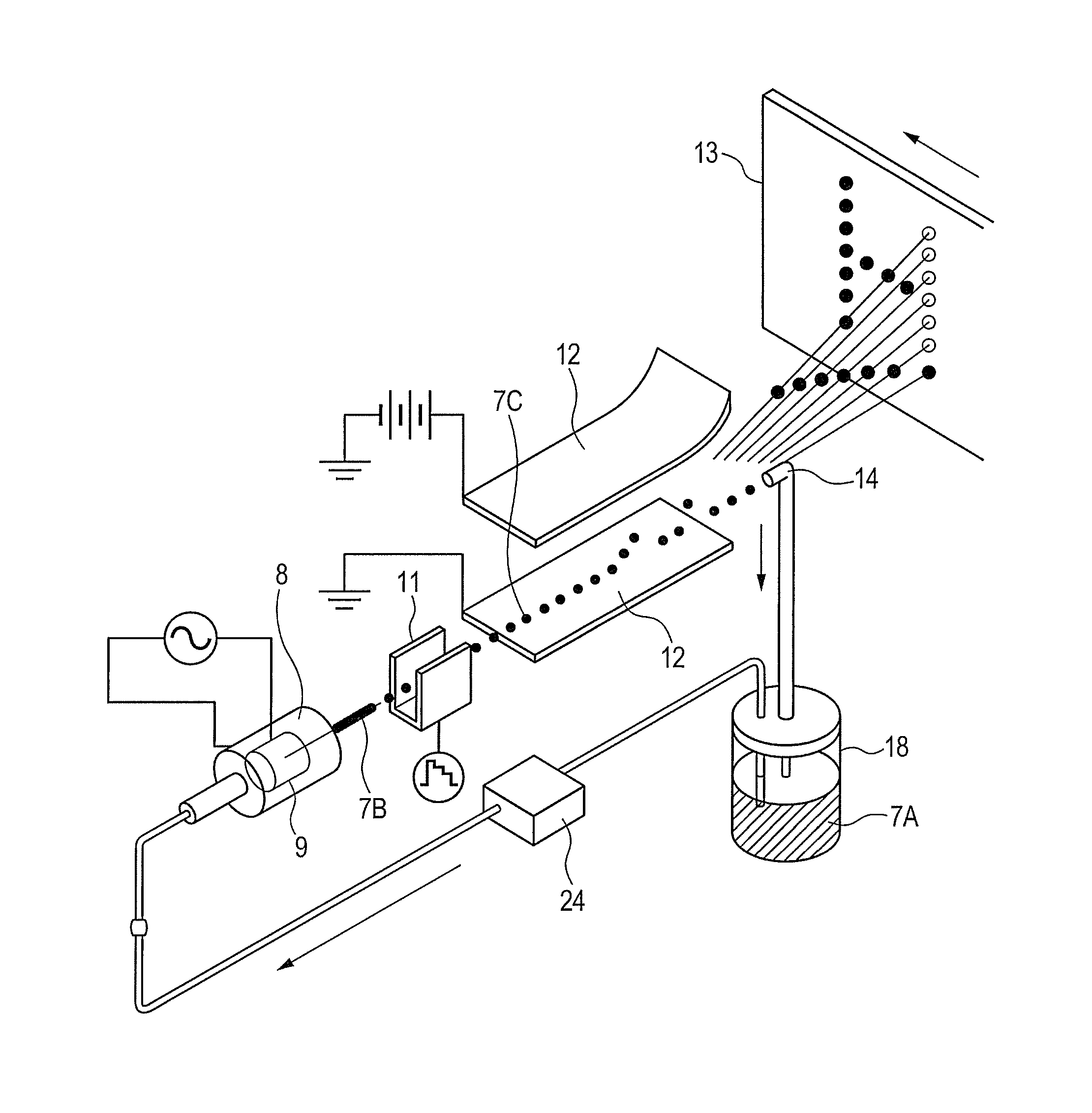
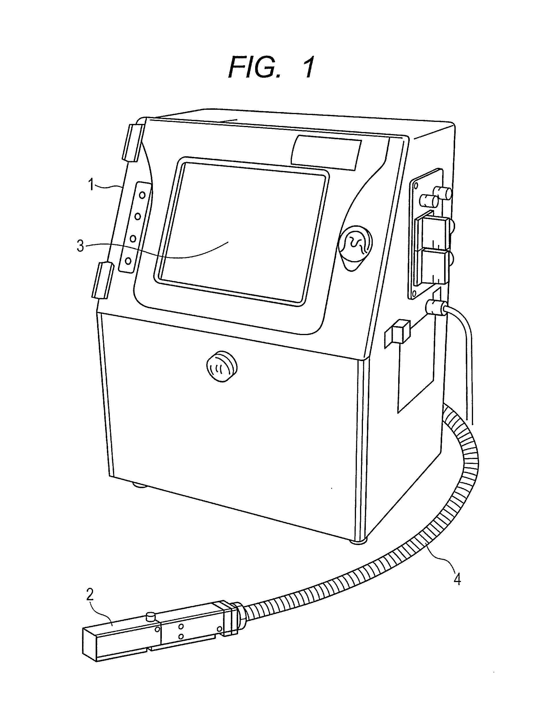
[0062]FIG. 1 is a perspective view of an appearance of an inkjet recording apparatus according to the present invention. Referring to FIG. 1, a reference numeral 1 denotes a main body of the inkjet recording apparatus, 2 denotes a print head, 3 denotes an operation display unit, and 4 denotes a cable. The main body 1 of the inkjet recording apparatus includes the operation display unit 3, and the print head 2 provided outside. The main body 1 and the print heat 2 are connected via the cable 4.

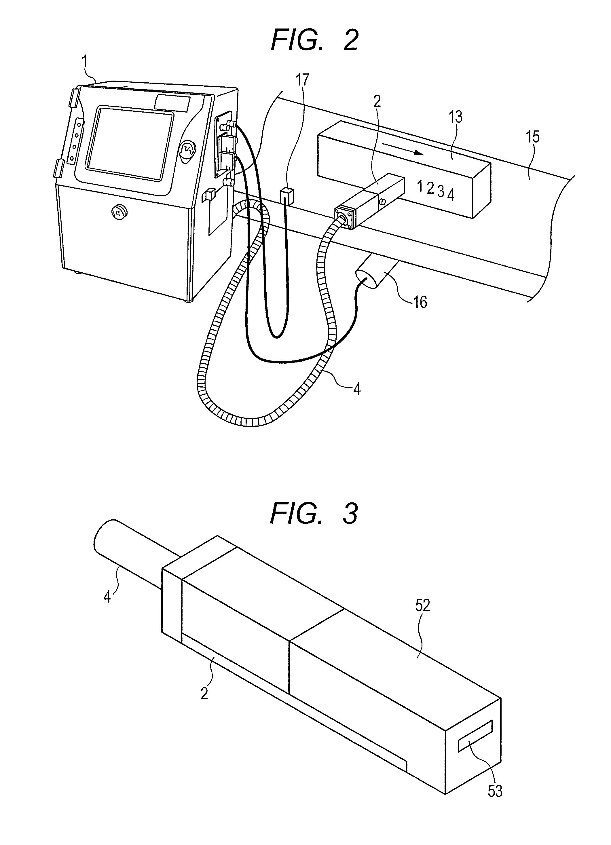
[0063]A state where the inkjet recording apparatus is used will be described referring to FIG. 2. As FIG. 2 shows, the reference numeral 1 denotes the main body of the inkjet recording apparatus, 2 denotes the print head, 4 denotes the cable, 13 denotes an object subjected to printing of a numeral and a character, 15 denotes a belt conveyor which conveys the object to be printed, 16 denotes a rotary encoder which measures a conveyance distance of the belt conveyor 15, and 17 denotes a printing ...

second example

[0087]A second example according to the present invention will be described referring to FIGS. 9A to 9D, and 10. FIG. 9A is an overall sectional view of a gas-liquid separator 100B. FIG. 9B is a view of FIG. 9A seen from a direction E. FIG. 9C is a view of FIG. 9A seen from a direction F. FIG. 9D is a sectional view of the chamber center taken along line G-G of FIG. 9A. FIG. 10 is an enlarged view of a dotted frame H shown in FIG. 9A. Referring to FIG. 9A, a reference numeral 131 denotes a gas outlet pipe, 122 denotes a casing through which the gas outlet pipe 131 is inserted and fixed, 132 denotes a gas-liquid 2-phase inlet pipe, 133 denotes a gas-liquid outlet pipe, 121 denotes a casing through which the gas-liquid 2-phase inlet pipe 132 and the gas-liquid 2-phase outlet pipe 133 are inserted and fixed, 121A denotes a chamber, 123 denotes a block provided inside the chamber 121A. Use of the resin material for forming the block 123 allows easy manufacturing through molding.

[0088]Wh...

third example

[0092]A third example according to the present invention will be described referring to FIGS. 11A to 11D, and 12. FIG. 11A is an overall sectional view of a gas-liquid separator 100C. FIG. 11B is a view of FIG. 11A seen from a direction J. FIG. 11C is a view of FIG. 11A seen from a direction K. FIG. 11D is a sectional view of the chamber center taken along line L-L of FIG. 11A. FIG. 12 is an enlarged view of a dotted frame M of FIG. 11A. Referring to FIG. 11A, a reference numeral 151 denotes a gas-liquid 2-phase inlet pipe, 152 denotes a gas outlet pipe, 153 denotes a gas-liquid 2-phase outlet pipe, 142 denotes a casing through which the gas-liquid 2-phase inlet pipe is inserted and fixed, 141 denotes a casing through which the gas outlet pipe 152 and the gas-liquid 2-phase outlet pipe 153 are inserted and fixed, and 143 denotes a porous plate provided in the chamber 141A. When forming the gas-liquid separator 100C, the casings 142 and 141 are fit and combined to form the enclosure ...


PUM

PropertyMeasurementUnit
heightaaaaaaaaaa
distanceaaaaaaaaaa
pressureaaaaaaaaaa

Abstract

A gas-liquid separator includes a casing with a cylindrical chamber inside, a gas-liquid 2-phase inlet pipe which is attached to a wall of the casing and connected to the chamber, a gas outlet pipe for discharging the gas of a gas-liquid mixture flowing into the chamber, and the gas-liquid 2-phase outlet pipe for discharging the liquid as a most part of the gas-liquid mixture flowing into the chamber. A gap is formed around the gas-liquid outlet pipe in the chamber for separating the mixture into liquid and gas using the surface tension and suction force. The gas-liquid separator is installed in the inkjet recording apparatus, especially in the print head. The print head is filled with the solvent gas so as to be suctioned from the gutter to reduce the solvent consumption.

Description

CLAIM OF PRIORITY[0001]The present application claims priority from Japanese Patent Application JP 2012-175880 filed on Aug. 8, 2012, the content of which is hereby incorporated by reference into this application.BACKGROUND[0002]The present invention relates to a gas-liquid separator and an inkjet recording apparatus using the gas-liquid separator.[0003]JP-A-2009-172932 as background of the relevant technical field discloses an inkjet recording apparatus of continuous type configured to charge only particles of ink ejected through a nozzle for printing using a charged electrode, deflect a flight direction of the charged ink particles using the deflection electrode for printing, and recover the ink particles unused for printing through suction by the gutter so as to be used for printing again. Upon suction of the ink particles for recovery, the gutter suctions air around the ink particles together. The suctioned air is continuously fed into the ink container, thus requiring the struc...

Claims


Application Information

Patent Timeline
Patent Type & Authority Patents(United States)
IPC IPC(8): B41J2/17B01D19/00B41J2/19B41J2/185B41J29/38B41J2/18
CPCB41J2/19B01D19/0042B41J2/18B41J2/185B41J29/38B41J2002/1853B41J2/01B41J2/165B41J2/16517
Inventor ARIMA, TAKAHIROMIYAO, AKIRAIGARI, MITSUOOKANO, MAMORUINOUE, TOMOHIRO
Owner HITACHI IND EQUIP SYST CO LTD
Why Eureka
Try Eureka