Fixing arrangement for a hoisting machine, and elevator assembly

a technology for fixing solutions and hoisting machines, which is applied in the direction of elevators, magnetic circuit rotating parts, and shape/form/construction of magnetic circuits, etc. it can solve the problems that the hoisting machine is not easily able to bend around the longitudinal axis of the support structure, and achieve the effect of increasing the rigidity reducing the size of the hoisting machine, and maximizing the efficiency of space utilization

Active Publication Date: 2016-04-12
KONE CORP
View PDF36 Cites 4 Cited by
  • Summary
  • Abstract
  • Description
  • Claims
  • Application Information

AI Technical Summary

Benefits of technology

[0005]The aim of the invention is to disclose a solution to the problem for increasing the rigidity of a hoisting machine fixed to a support structure in the elevator hoistway, more particularly when the size of the hoisting machine decreases. In connection with this, the invention also discloses a solution to the problem for maximizing the efficiency of utilization of the space of an elevator hoistway, taking into account the rigidity requirements for a hoisting machine and for a support structure of the hoisting machine.
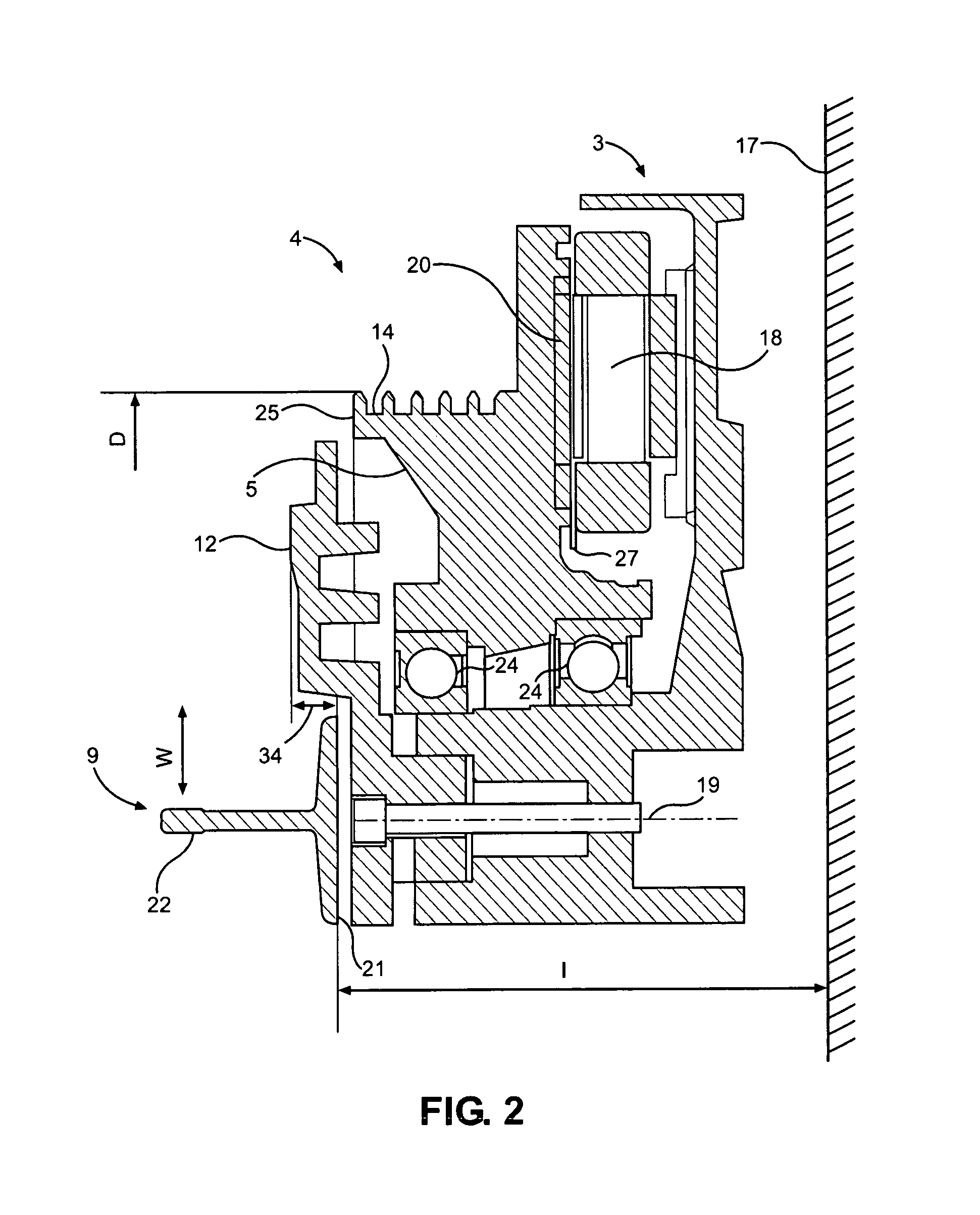
[0006]In the fixing arrangement for a hoisting machine according to the invention the hoisting machine comprises a stationary structure as well as a rotating structure. The rotating structure comprises a traction sheave, which comprises a traction surface for exerting a force effect. In the fixing arrangement the hoisting machine is fixed with fixing means to an elongated support structure. The elongated support structure is preferably continuous in the vertical direction, e.g. a guide rail of the elevator car or of the counterweight. The hoisting machine is fixed from at least two points that are situated apart in the width direction of the support structure for damping the vibration caused by the operation of the hoisting machine. The aforementioned fixing points are preferably disposed in the top part of the hoisting machine and at essentially the same height as each other. The aforementioned fixing points are preferably situated at a distance from each other of at least the width of the support structure and on different sides of the support structure. The hoisting machine is connected from its fixing points to a fixing means / to fixing means with dampers that are preferably of elastomer. The fixing means is / are fixed rigidly to the support structure. Consequently, when the fixing points with their dampers are spread by at least the width of the support structure apart from each other, the hoisting machine is not easily able to bend around the longitudinal axis of the support structure. This makes it possible that the hoisting machine does not need to be as rigid as the type of prior-art hoisting machine that is fixed only at the point of the support structure in order to meet a certain bending criterion. Consequently, the rigidity needed can be achieved with a hoisting machine of a more lightweight structure than prior-art, or the rigidity of a hoisting machine can be improved compared to what it was before by using a fixing arrangement according to the invention.
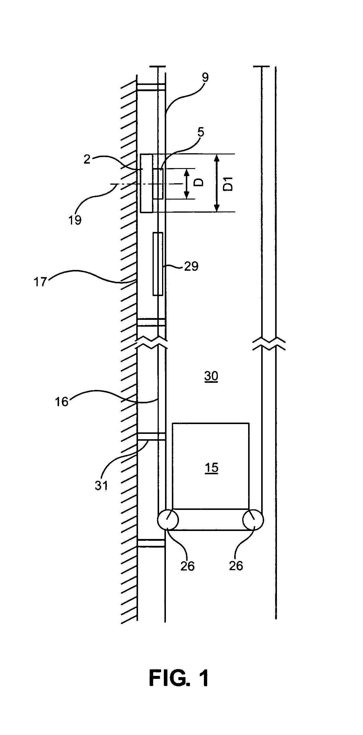
[0007]The distance between the aforementioned fixing points is preferably greater than, or equal to, the diameter of the traction sheave. The solution effectively damps vibrations of the hoisting machine, more particularly bending vibrations that are caused by a force (in an emergency stop situation, et cetera) exerted on the traction sheave and that occur in relation to the longitudinal axis of the support structure, because the fixing points resist the vibration by exerting a force opposing the vibration, the lever arm of which force for the bending occurring in relation to the longitudinal axis of the support structure is, owing to the distance between the fixing points, at least as large as or larger than the lever arm of the force exerted on the traction sheave and producing the vibration. In this way the dimensioning of the fixing points in relation to the force exerted on the fixing points can be reduced, in which case the fixing points / dampers connected to the fixing points can, if necessary, be made structurally lighter than those according to prior art.
[0017]The slot number q of the concentrated fractional-slot winding in the stator of the hoisting machine is most preferably 0.3. When the slot number of the elevator motor that functions as the power-producing part of the hoisting machine decreases, the number of stator slots in relation to the number of rotor poles also decreases. When the number of stator slots decreases, the space needed by the stator winding, and more particularly by the winding overhangs, also decreases. In this case the hoisting machine can be fixed to a guide rail of the elevator car in connection with a wall part of the elevator hoistway in a smaller space than prior art. For increasing the rigidity of the hoisting machine, the hoisting machine can be fixed using the fixing arrangement for a hoisting machine described in the preceding. A suspension ratio of 2:1, or even greater, can further be selected as the suspension ratio of the elevator assembly, and the force exerted, via the traction surface of the traction sheave, on the guide rail supporting the hoisting machine can therefore be reduced. When the distance of the guide rail supporting the hoisting machine is further selected, in the manner presented in the invention, as a function of the nominal load, i.e. of the maximum load during normal operation, of the elevator car, the space box of the elevator car in the elevator hoistway can be increased and therefore the usable cross-sectional area of the elevator hoistway can be utilized more efficiently than in prior art. The invention is applicable for use in elevator assemblies with counterweight; the space advantage to be achieved with the invention can, however, also be utilized by applying the invention to elevator assemblies without counterweight.

Problems solved by technology

Consequently, when the fixing points with their dampers are spread by at least the width of the support structure apart from each other, the hoisting machine is not easily able to bend around the longitudinal axis of the support structure.

Method used


Image

  • Fixing arrangement for a hoisting machine, and elevator assembly
  • Fixing arrangement for a hoisting machine, and elevator assembly
  • Fixing arrangement for a hoisting machine, and elevator assembly

Examples


Embodiment Construction

[0031]FIG. 1 presents as a block diagram an elevator assembly, in which the elevator car 15 and the counterweight 29 are suspended in the elevator hoistway 30 with suspension ropes 16. The elevator car 15 is moved with the hoisting machine 2 of the elevator, said hoisting machine being disposed in the top part of the elevator hoistway 30, along a guide rail 9 fixed to a wall part 17 of the elevator hoistway by exerting a force effect on the elevator car with hoisting ropes 16 traveling via the traction sheave 5 of the hoisting machine 2 of the elevator. On the surface of the traction sheave 5 are rope grooves, in which the hoisting ropes move along with the rotational movement of the traction sheave such that the hoisting ropes are rotatably supported in the rope grooves. The power supply to the hoisting machine 2 of the elevator occurs with a frequency converter (not shown in figure) connected between an electricity network and the hoisting machine 1 of the elevator. The frequency ...


PUM


Abstract

The invention relates to a fixing arrangement of a hoisting machine, in which arrangement the hoisting machine comprises a stationary structure as well as a rotating structure; which rotating structure comprises a traction sheave, which comprises a traction surface for exerting a force effect; and in which fixing arrangement the hoisting machine is fixed with fixing means to an elongated support structure such that the hoisting machine is fixed to the support structure from at least two points that are situated apart in the width direction (w) of the support structure for damping the vibration caused by the operation of the hoisting machine.

Description

CROSS REFERENCE TO RELATED APPLICATIONS[0001]This is a continuation of PCT / FI2011 / 050549 filed Jun. 10, 2011, which is an International Application claiming priority to FI 20105661 filed on Jun. 10, 2010, the entire contents of each of which are hereby incorporated by reference.FIELD OF THE INVENTION[0002]The invention relates to fixing solutions and support solutions for a hoisting machine.BACKGROUND OF THE INVENTION[0003]It is a general aim to utilize built space as efficiently as possible. For example, owing to space requirements, one aim is to make the hoisting machines of elevators as compact as possible. In order to achieve this, hoisting machines are designed to be as flat as possible in their dimensions in the direction of the axis of rotation or as small as possible in their dimensions in the direction of the radius, in which case the hoisting machines fit better in connection with, for instance, the wall part of the elevator hoistway or into some other narrow / shallow space...

Claims


Application Information

Patent Timeline
Patent Type & Authority Patents(United States)
IPC IPC(8): B66B11/08B66B11/04B66B11/00H02K1/16B66B7/06H02K21/24H02K1/27H02K7/10
CPCB66B11/0045B66B11/0438H02K1/16B66B11/008H02K1/2793H02K7/1008H02K21/24H02K1/2795
Inventor TENHUNEN, ASMOALKULA, PETRIHUPPUNEN, JUSSIVIRNES, MIKASIMBIEROWICZ, GABRIELA
Owner KONE CORP
Why Eureka
Try Eureka