
Multi-fluid precision calibration pressure source

a pressure source and flue technology, applied in the direction of positive displacement liquid engines, piston pumps, instruments, etc., can solve the problems of difficult to fine-tune pressure levels, large torque to close, and the seal of check valves is often prone to rapid failure, so as to reduce the risk of leakage, and reduce the effect of leakag

Active Publication Date: 2016-04-12
KING NUTRONICS LLC (A DELAWARE LLC)
View PDF48 Cites 7 Cited by
  • Summary
  • Abstract
  • Description
  • Claims
  • Application Information

AI Technical Summary

Benefits of technology

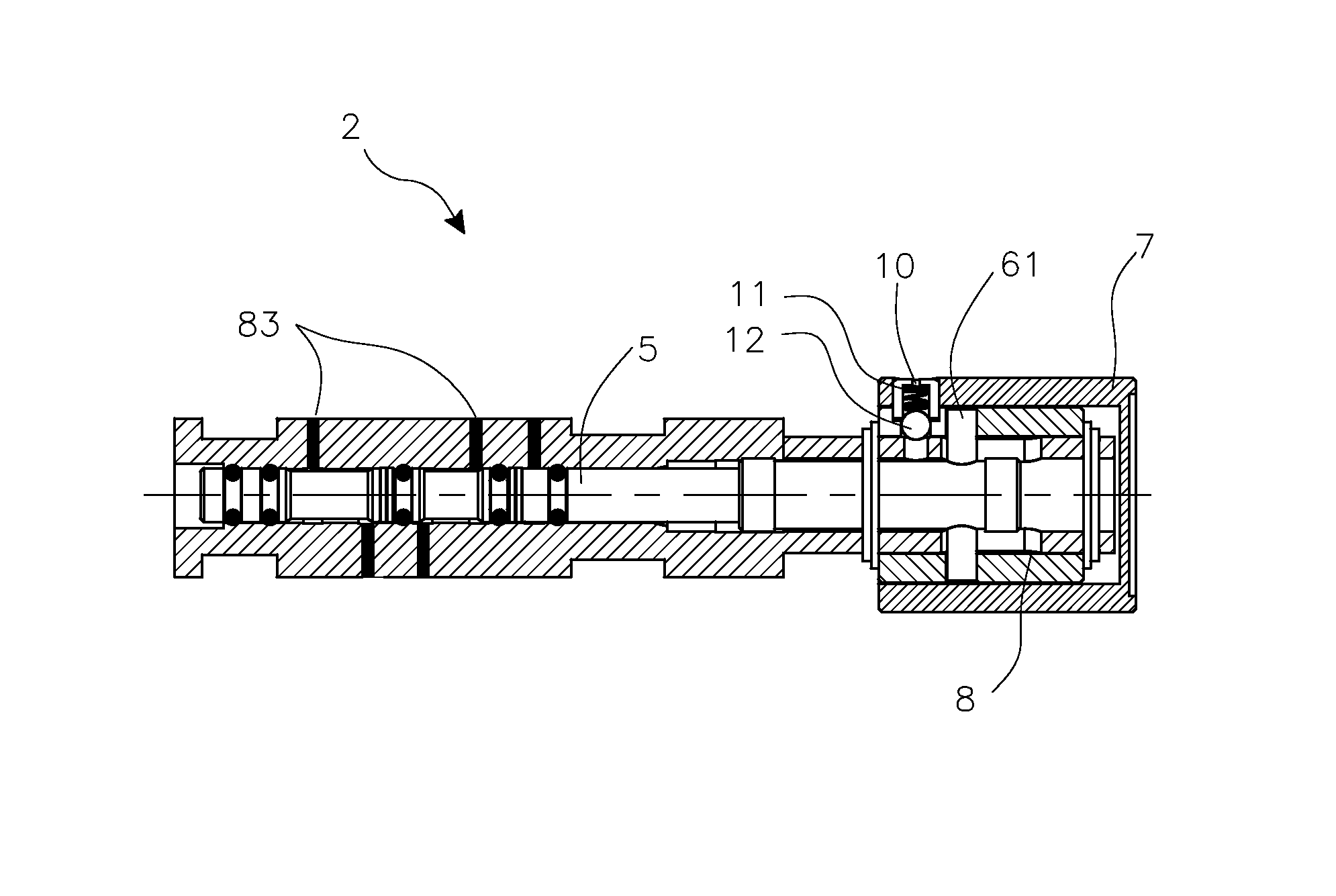
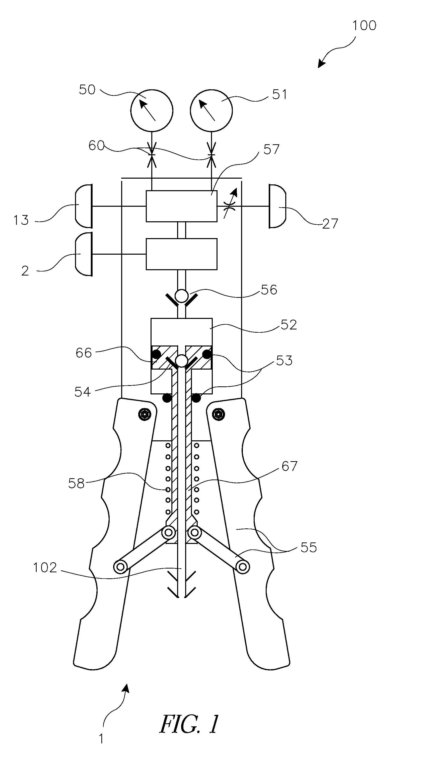
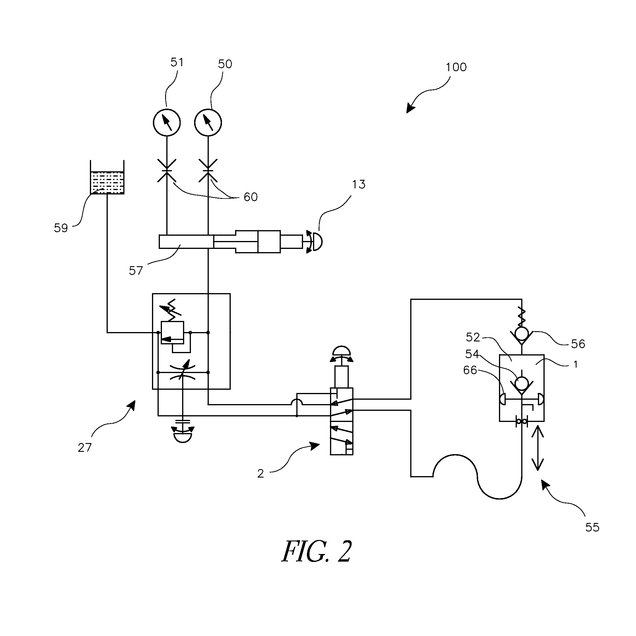
The patent text describes various improvements to calibration pressure devices. These improvements include a micro metering bleed valve for finely controlled pressure release in both pneumatic and hydraulic applications, a unidirectional slip clutch to prevent damage to the bleed valve, a combination of a micro metering bleed valve and a pressure release valve to save space and weight, and a mode selector valve for easy switching between vacuum and pressure modes. The patent also describes a portable calibration pressure device with a pump, manifold, volume adjuster, and secondary piston. The volume adjuster has a primary knob and a secondary knob for easy adjustment, and the secondary piston blocks an end of the cylindrical cavity to form a chamber that fluidly communicates with the first and second ports. The technical effects of these improvements include improved accuracy, durability, and versatility of calibration pressure devices.

Problems solved by technology

Such seals require a very large torque to close, making it difficult to fine tune pressure levels, and they quickly bleed gas when opened in a pneumatic application.
Because calibration pressure devices frequently operate at high pressures, the seals on check valves are frequently prone to rapid failure.
However, in many current devices a volume adjuster that works well for pneumatic applications by making a relatively large volume adjustment requires a significant torque in order to adjust volume in hydraulic applications.
Additionally, current devices that do attempt to provide both vacuum and pressure modes often use metal seals used when switching between vacuum and pressure modes, and the operator must provide a significant torque to switch between modes.

Method used


Image

  • Multi-fluid precision calibration pressure source
  • Multi-fluid precision calibration pressure source
  • Multi-fluid precision calibration pressure source

Examples


Embodiment Construction

[0060]In various embodiments described herein, calibration pumps can be used for calibrating pneumatic and hydraulic gauges, switches and other instruments. There are many types of pumps and calibration pressure sources. In some embodiments, the pump can be a hand operated pump suitable for portable applications. In some embodiments, the calibration pumps can combine hydraulic and pneumatic calibration capabilities, providing fine adjustment capabilities for gases and liquids in the same unit and providing pressure adjustment without requiring excessive operator force. This can help allow technicians to carry a single calibration device instead of one device for pneumatic and one device for hydraulic applications.

[0061]In various embodiments described herein, calibration pumps can be used as a pressure and / or a vacuum source for calibrating pneumatic and hydraulic gauges, switches and other instruments. These embodiments can also allow a technician to carry a single device for multi...


PUM

PropertyMeasurementUnit
pressuresaaaaaaaaaa
angleaaaaaaaaaa
angleaaaaaaaaaa

Abstract

A pressure calibration device can include certain features that allow it to be used with a variety of hydraulic and pneumatic systems. A pressure calibration device can be configured to provide pressure or vacuum, and can have a mode selector for selecting to provide pressure or vacuum. A pressure calibration device can have a volume adjuster configured to modify pressures for hydraulic or pneumatic systems. A pressure calibration device can have a pressure release valve and a bleed valve for adjusting pressure values.

Description

CROSS-REFERENCE TO RELATED APPLICATIONS[0001]This application is related to and claims priority to U.S. Provisional Application No. 61 / 601,872, filed Feb. 22, 2012, the entire application of which is hereby incorporated by reference and made a part of this specification.BACKGROUND[0002]1. Field[0003]Various embodiments disclosed herein relate generally to devices and methods for calibrating pressures in systems and devices.[0004]2. Related Art[0005]Current calibration pressure devices use various types of volume adjusters and bleed valves that are usually designed exclusively for either pneumatic or hydraulic applications. Because of the significant different pressure values involved, valves and adjusters that work well in hydraulic applications may not work as well in pneumatic applications and vice versa.[0006]Many current devices do not operate both as a pressure source and as a vacuum source for calibration. Those that do have various limitations and disadvantages.SUMMARY OF THE...

Claims


Application Information

Patent Timeline
Patent Type & Authority Patents(United States)
IPC IPC(8): G01L27/00F04F1/00
CPCF04F1/00G01L27/005Y10T137/86083F04B7/02F16K11/0704F16K31/528F16K17/04F16K15/026F04B37/12F04B37/14
Inventor GNESSIN, AMIRWELTHER, ROBERT T
Owner KING NUTRONICS LLC (A DELAWARE LLC)
Learn More