Multilayer hydraulic seal assembly for clamp

a multi-layer, hydraulic seal technology, applied in fluid pressure sealing joints, engine seals, sleeve/socket joints, etc., to achieve the effect of improving the degree of sealing, facilitating one-to-one contact, and increasing the tightness of the seal

Active Publication Date: 2016-04-12
KRAUSZ IND
View PDF16 Cites 15 Cited by
  • Summary
  • Abstract
  • Description
  • Claims
  • Application Information

AI Technical Summary

Benefits of technology

[0005]The present invention seeks to provide an improved multilayer hydraulic sealing assembly, as is described more in detail hereinbelow. In accordance with an embodiment of the present invention, the seal assembly includes a first ring seal seated over a second ring seal; unlike the prior art, both seals have inner spaces for fluid to flow therein to apply pressure to increase tightening of the seal and improve the degree of sealing. The seals can be easily disconnecting from one another to allow sealing against different diameter pipes.

Problems solved by technology

However, the second ring seal used for smaller diameter pipes does not have such an inner space.

Method used


Image

  • Multilayer hydraulic seal assembly for clamp
  • Multilayer hydraulic seal assembly for clamp

Examples


Embodiment Construction

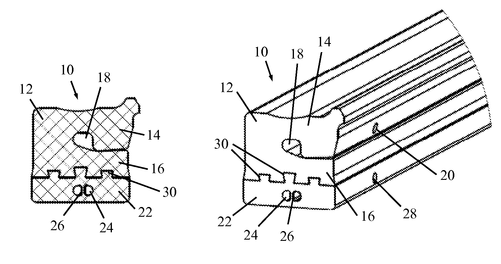
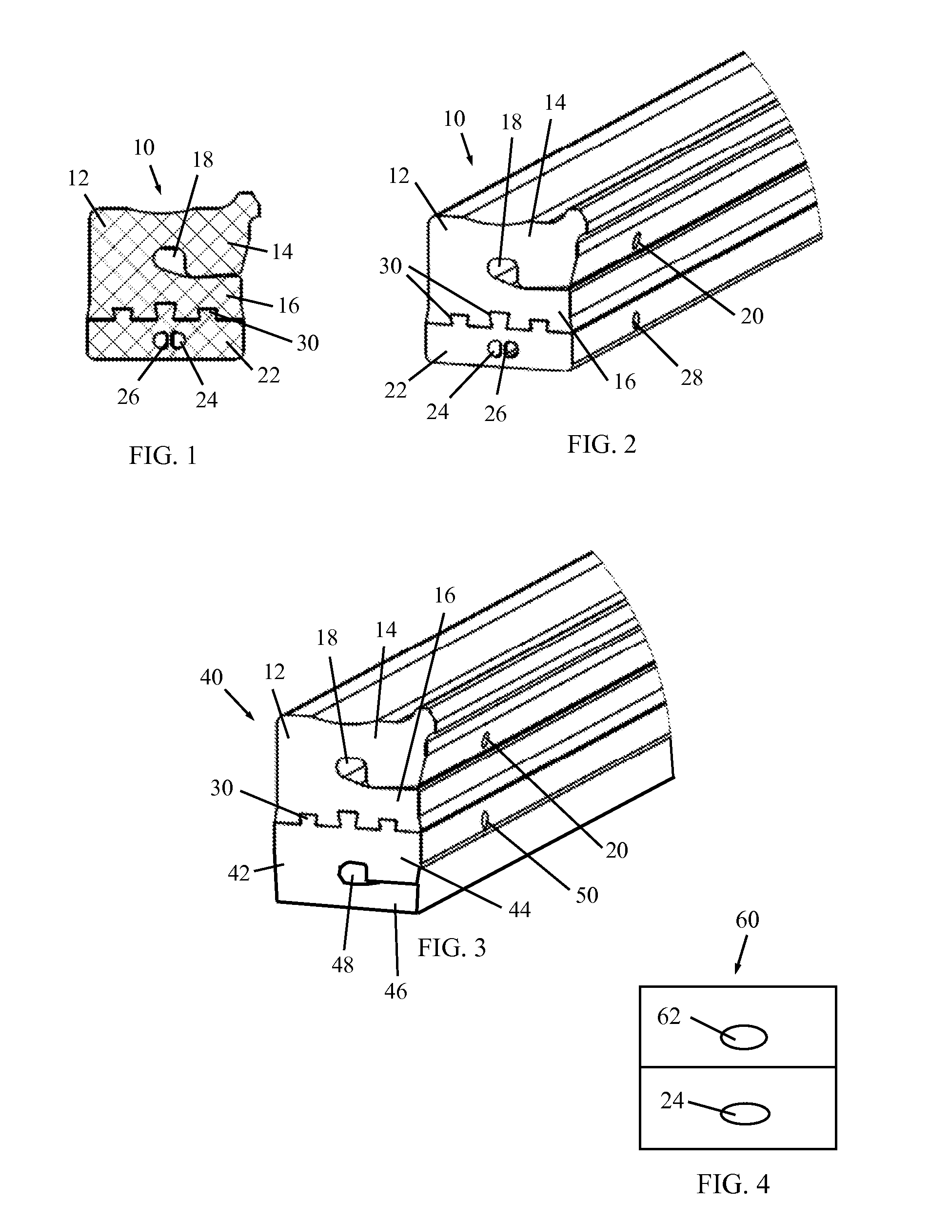
[0014]Reference is now made to FIGS. 1 and 2, which illustrate a multilayer hydraulic seal assembly 10, constructed and operative in accordance with a non-limiting embodiment of the present invention. The material of the seal may have a cross-hatched design as in FIG. 1, or smooth as is FIG. 2, or any other design.

[0015]Seal assembly 10 is particularly useful in a clamp of the type of U.S. Pat. No. 6,293,556, but the invention is not limited to this type of clamp.

[0016]Seal assembly 10 includes at least one outer sealing ring 12 constructed with an outer portion 14 folded over an inner portion 16 so as to define at least one inner annular space 18 between and bounded by the inner and outer portions 16 and 14. The inner annular space 18 is in fluid communication with a fluid (e.g., water, not shown) flowing in a pipe sealed by seal assembly 10. The fluid enters inner annular space 18 via one or more apertures 20 formed in a side wall of outer sealing ring 12 (preferably through the i...


PUM


Abstract

A multilayer annular seal assembly including at least one outer sealing ring including at least one inner annular space and at least one inner sealing ring formed with one or more inner annular chambers.

Description

FIELD OF THE INVENTION[0001]The present invention relates generally to clamps and grip rings for pipes, and particularly to a multilayer hydraulic seal assembly for a clamp.BACKGROUND OF THE INVENTION[0002]Many kinds of removable band-type couplings for pipes exist in the art. It is noted that throughout the specification and claims, the term “pipe” encompasses any kind of generally cylindrical object.[0003]U.S. Pat. No. 6,293,556 to Krausz describes a coupling for connecting pipes of the same or different diameters. The coupling has a ring shaped seal made of rubber or other resilient material, constructed of a first ring seal seated over a second ring seal. The seals can be easily disconnected from one another to allow sealing against different diameter pipes. For smaller diameter pipes, both the first and second ring seals are used; for larger diameters, only one seal is used.[0004]In the prior art, the seal for the larger diameter has an inner space which is in fluid communicati...

Claims


Application Information

Patent Timeline
Patent Type & Authority Patents(United States)
IPC IPC(8): F16L17/00F16L17/10F16L17/035F16L21/06F16J15/48F16J15/02
CPCF16J15/025F16J15/027F16L17/10F16J15/48F16L17/00F16L17/035F16L21/06
Inventor CHIPROOT, AVIKRAUSZ, DANNY
Owner KRAUSZ IND
Why Eureka
Try Eureka