Protective assembly and method for mounting same, upright and sleeve of such a protective assembly

a protective kit and assembly technology, applied in the direction of mechanical equipment, manufacturing tools, rod connections, etc., can solve the problems of high final cost and maintenance costs, long realization time on site, and the use of welding machines and specific protections, so as to reduce the risk of work-related injuries and reduce the manufacturing and maintenance costs of the protection kit manufactured in this way

Active Publication Date: 2013-08-15
CITYNOX
View PDF3 Cites 0 Cited by
  • Summary
  • Abstract
  • Description
  • Claims
  • Application Information

AI Technical Summary

Benefits of technology

[0009]Thanks to these provisions, a protection kit can be constituted by inserting a sleeve into a post, thanks to the deformation of the tabs, then by inserting a rail in the sleeve. By avoiding the need for welding, the manufacturing and maintenance costs of the protection kits manufactured in this way are reduced and the risk of work-related injuries is reduced.

Problems solved by technology

Their realization time on site is consequently very long and requires the use of welding machines and specific protections.
The final cost as well as the maintenance costs are therefore very high.

Method used


Image

  • Protective assembly and method for mounting same, upright and sleeve of such a protective assembly
  • Protective assembly and method for mounting same, upright and sleeve of such a protective assembly
  • Protective assembly and method for mounting same, upright and sleeve of such a protective assembly

Examples


Embodiment Construction

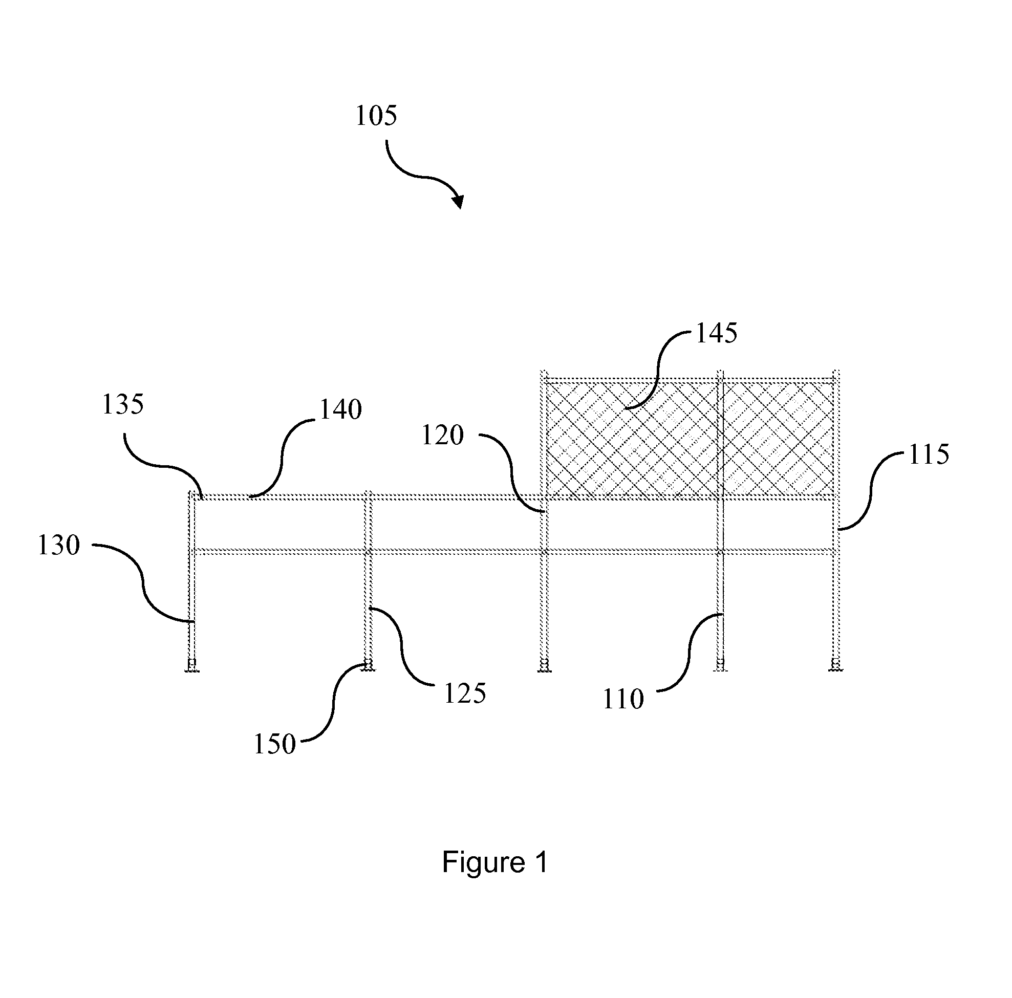
[0075]FIG. 1 shows a protection kit 105 comprising upper posts 110, 115 and 120, lower posts 125 and 130, sleeves 135, rails 140, fencing or meshing 145 and feet 150.

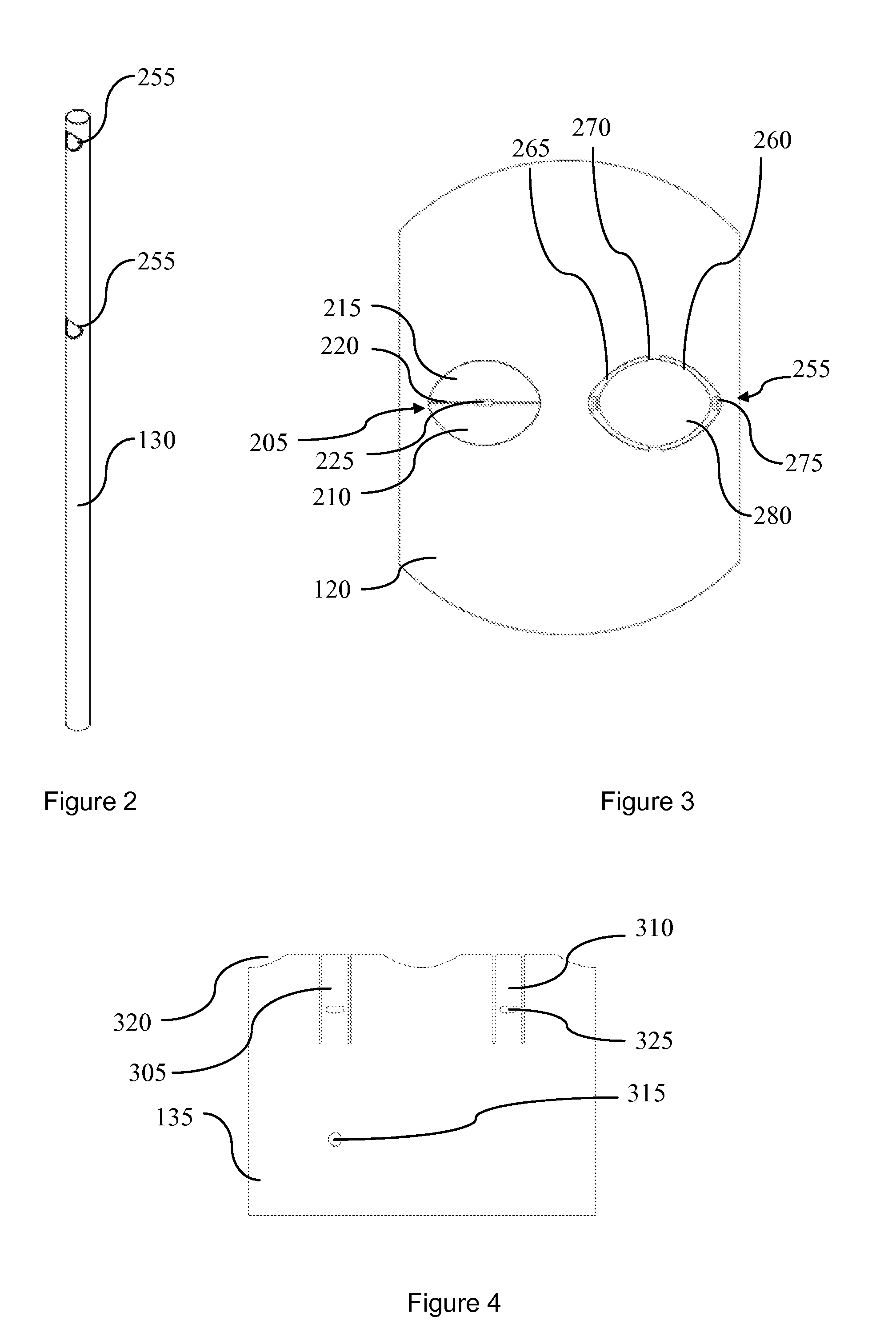
[0076]All these elements are preferably metallic, for example made of stainless steel. The sleeves 135 are described with reference to FIG. 4. The fencing or mesh 145 is assembled as illustrated in FIG. 17. The feet 150 are described with reference to FIGS. 18 and 19.

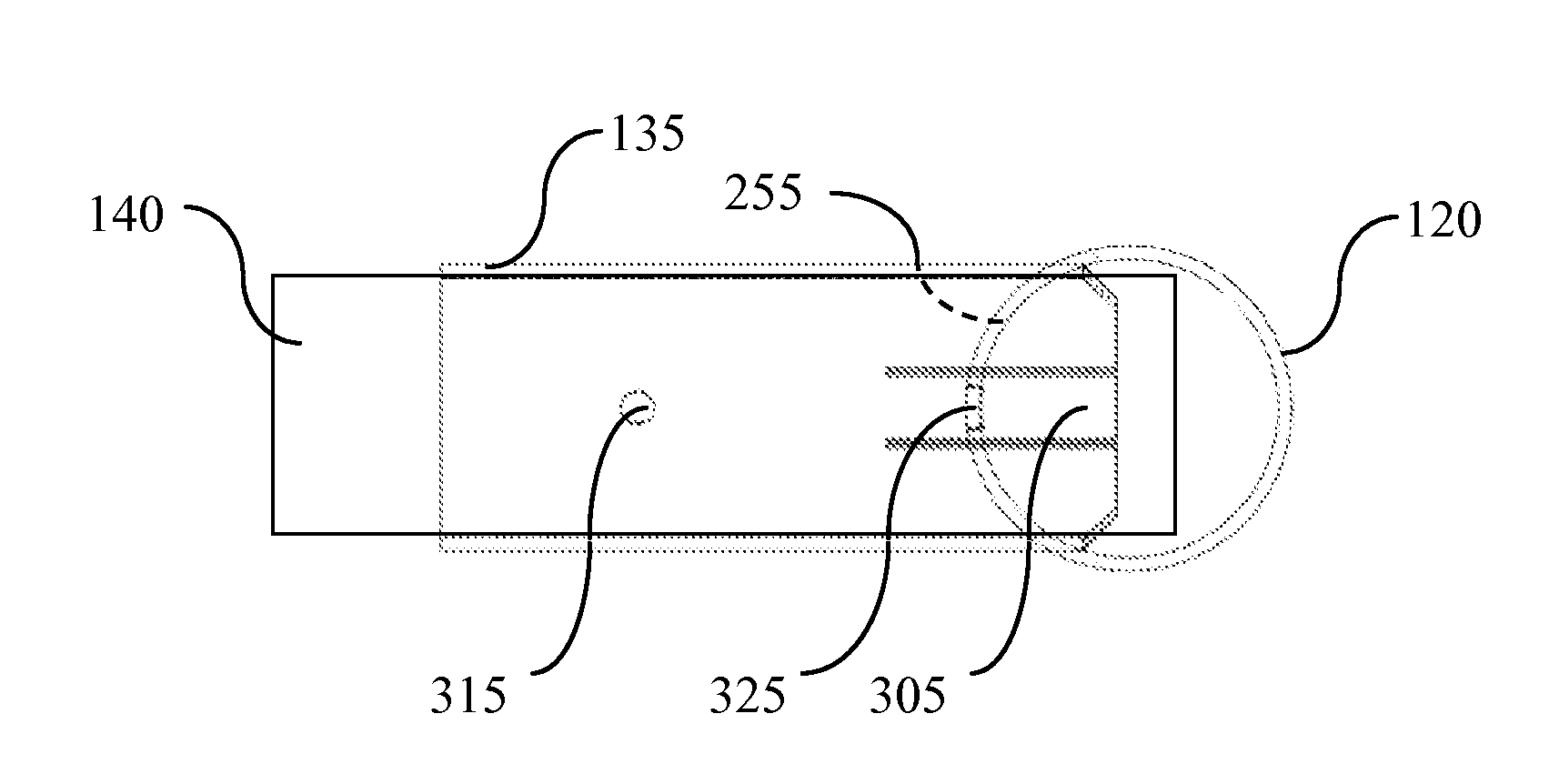
[0077]The upper post 110 and the lower post 125 are called “pass-through posts” because all the rails 140 pass through them. The upper post 115 and the lower post 130 are called “extremity posts” because all the rails 140 that reach them end there. The post 120 is called “mixed post” because the upper rail ends there, whereas the lower rails pass through it.

[0078]The sleeves 135 are present every time a rail ends, except if another rail comes after it, as illustrated in FIG. 16. In contrast, a rail passing through a post comprises no sleeve.

[0079]In the fig...


PUM

PropertyMeasurementUnit
diameteraaaaaaaaaa
right anglesaaaaaaaaaa
timeaaaaaaaaaa

Abstract

The protection kit comprises at least one post comprising at least one side opening, at least one rail, and at least one sleeve comprising at least one deformable tab. The sleeve is operable to receive a rail within its interior and to enter a side opening with deformation of at least one tab. Preferably, at least one opening is fitted with a tooth and the tab is deformable elastically and comprises an opening to receive the tooth. The insertion of a sleeve into the opening of the post causes the tab to deform until the tooth is located in the opening of the tab and the insertion of the rail into the interior of the sleeve restrains the tab.

Description

RELATED APPLICATIONS[0001]This application is a §371 application from PCT / FR2011 / 051419 filed Jun. 20, 2011, which claims priority from French Patent Application No. 10 54885 filed Jun. 18, 2010 and French Patent Application No. 10 54879 filed Jun. 18, 2010, each of which is herein incorporated by reference in its entirety.TECHNICAL FIELD OF INVENTION[0002]This invention relates to a protection kit and its method of assembly, a post and a sleeve for such a protection kit. It applies to all protections of persons, wall protections, in particular for street furniture in public or private locations.BACKGROUND OF THE INVENTION[0003]Barriers known from the prior state of the art are made of metal parts welded together. Their realization time on site is consequently very long and requires the use of welding machines and specific protections. The final cost as well as the maintenance costs are therefore very high.OBJECT AND SUMMARY OF THE INVENTION[0004]The aim of this invention is to reme...

Claims


Application Information

Patent Timeline
Patent Type & Authority Applications(United States)
IPC IPC(8): E04H17/14
CPCE04H17/1421Y10T29/49826F16B7/0446E04H17/1443E04H17/1439E04H17/1447E04H17/1465E04H17/1417
Inventor RUSSIER, JONATHANMARTIGNE, BRICE
Owner CITYNOX
Why Eureka
Try Eureka