Card holding device

a card and holding device technology, applied in the field of card connecting and holding devices, can solve the problems of inability to meet the needs of low-profile card readers, and inability to operate, so as to facilitate the introduction of smart cards, facilitate the removal of smart cards, and reduce the total cost of manufacturing the electronic device using such a card holding device

Active Publication Date: 2016-04-12
SONY CORP
View PDF7 Cites 1 Cited by
  • Summary
  • Abstract
  • Description
  • Claims
  • Application Information

AI Technical Summary

Benefits of technology

[0024]Thus, the portable electronic device according to the invention comprises an integrated card holding device that serves as a smart and robust built-in-device in a card reader, which card holding device has no movable parts. The card holding device is fixed to the card reader and able to facilitate the removal of the smart card from the card holder or reader. The card holding device may also facilitate the introduction of the smart card into the card reader. It is an advantage with the invention that no movable parts are necessary for operating the card holding device, whereby there are fewer items that may break during removal and / or introduction of the smart card and be manufactured, kept track of, be stored and handled during manufacture of the card holding device and the card reader. Thus, also the total cost for manufacturing the electronic device using such a card holding device may be reduced. Furthermore, by being able to insert and remove the smart card from the card reader in the vertical direction, i.e., along a z-axis if the card reader defines an x-y-plane, through an opening between the card holding parts and their edges. This opening enables receiving and removing the smart card from the card reader by facing or “opening up” in the vertical direction of the card reader, i.e. in the normal direction of the plane of the card reader. This opening of the card reader makes the card reader fenestrated. This smart card access opening of the card reader is arranged within the footprint area of the card reader, the external space and / or area outside / around the card reader required for insertion and removal of the smart card is / are optimized, and even minimized, reducing the corresponding total footprint area (including the card reader itself) being reserved / necessary for this handling of the smart card. Furthermore, the detection switch being integrated in a chamfer area of the card reader prevents misinsertion of the smart card, i.e. a keying feature / function for the card is achieved. Moreover, the detection switch being integrated in the chamfer area of the card holding device and card reader saves space as the chamfer area is already existing occupying a certain volume inside the card reader, whereby no additional space is required for accommodating the detection switch. Furthermore, any openings and lids in the housing of the portable electronic device giving access to the card reader may be made smaller and are also easier to seal off against the surroundings due to the invention.

Problems solved by technology

Moreover, the housing of the portable electronic device may also have to be designed in a more complex way for enabling and accommodating both the manual handling and the unnecessary large foot-print area of the card reader, e.g., due to large openings in the housing and / or more complicated means / devices, e.g., with movable parts, allowing opening and closing of the housing, e.g., by means of openable / closable lids with varying complexity in sealings around the lids or similar means, for access of the card reader when introducing a smart card therein or removing a smart card therefrom.
This may give rise to problems for a user when introducing or removing a smart card, since any unevenness or hole may hook or get caught / jammed at the free end of the contact leg, whereby the contact leg is deformed and even destroyed so that it becomes inoperable.
One way of trying to solve this problem is to elongate the length of the free end or to orientate / place each contact leg such that there is a lesser risk of hooking thereon, but this may not be possible in low profile card readers as the available space, i.e., height is limited.
Hence, an extended free end would hit the bottom of the card reader before the contact leg is fully deflected, whereby the smart card would not fit inside the card reader or the contact leg would be deformed to an undesired extent.
This may give rise to problems for a user, since the smaller a smart card, a card reader or an electronic device equipped with these means the more difficult to introduce into and remove smart cards from card readers.
Known card readers without push-push or push-pull ejectors involve an increased cost for the manufacturer of the portable electronic device as a certain additional area and volume of the device in general is dedicated for accommodating the clearance around the card reader necessary for this making the electronic device larger than necessary.
When a portable electronic device is equipped with card readers comprising movable parts, these card readers are complicated and not that robust, increasing the risk of breakage of the movable parts.
The length of the protruding free end for known contact legs also involves an increased cost for the manufacturer of the portable electronic device as a certain additional volume of the device in general is dedicated for accommodating the height of the bent contact leg.
Moreover, any jamming of the smart card in the card reader may urge the user to use too much force when trying to introduce or withdraw the card, whereby the contact legs, the card and / or the card reader may be damaged.
Yet further, when a portable electronic device is to be equipped with a card reader, the handling and size of the portable electronic device are compromised as known contact legs, due to their shape, require a certain minimum height and foot-print area inside the card reader.

Method used


Image

  • Card holding device
  • Card holding device
  • Card holding device

Examples


Embodiment Construction

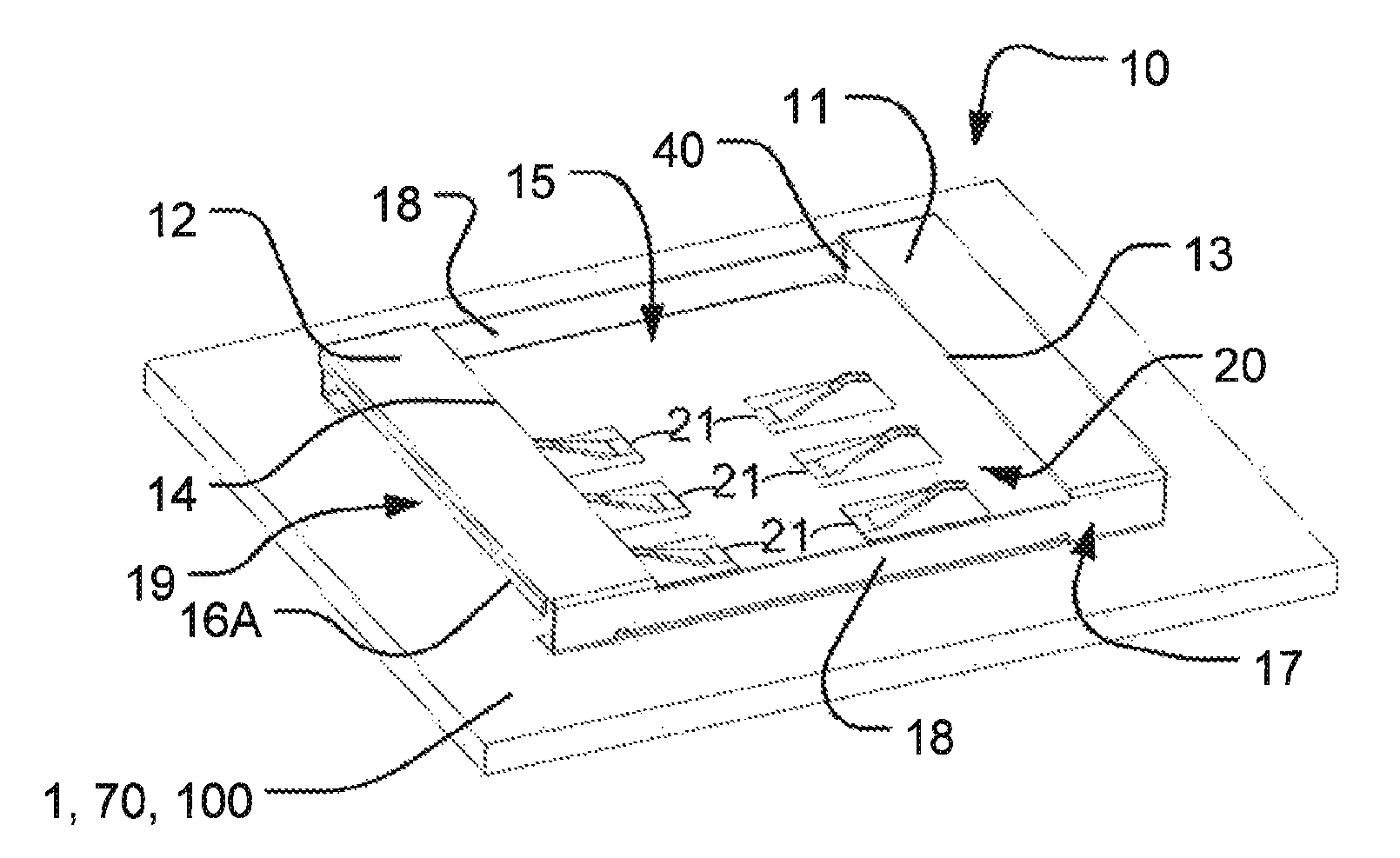
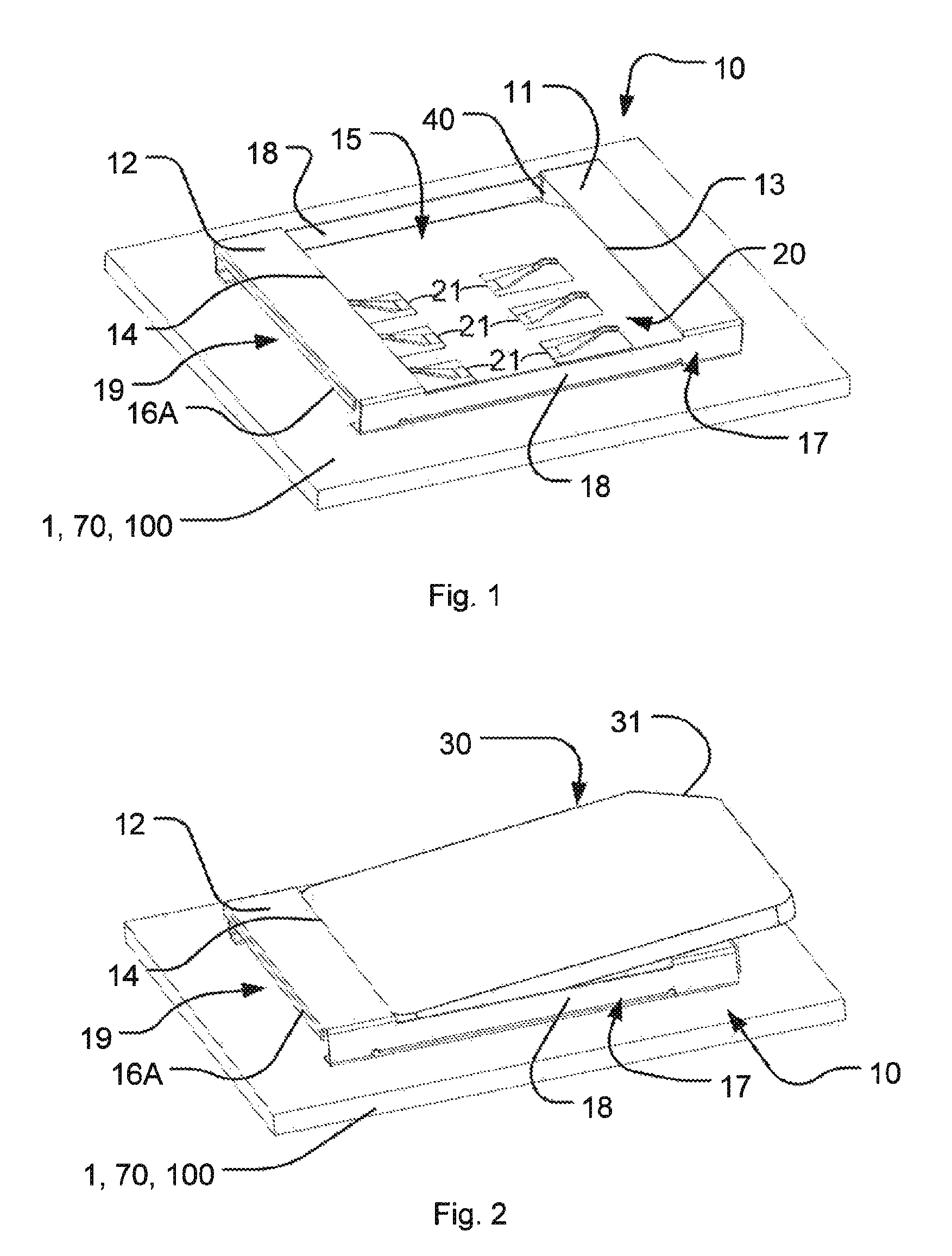
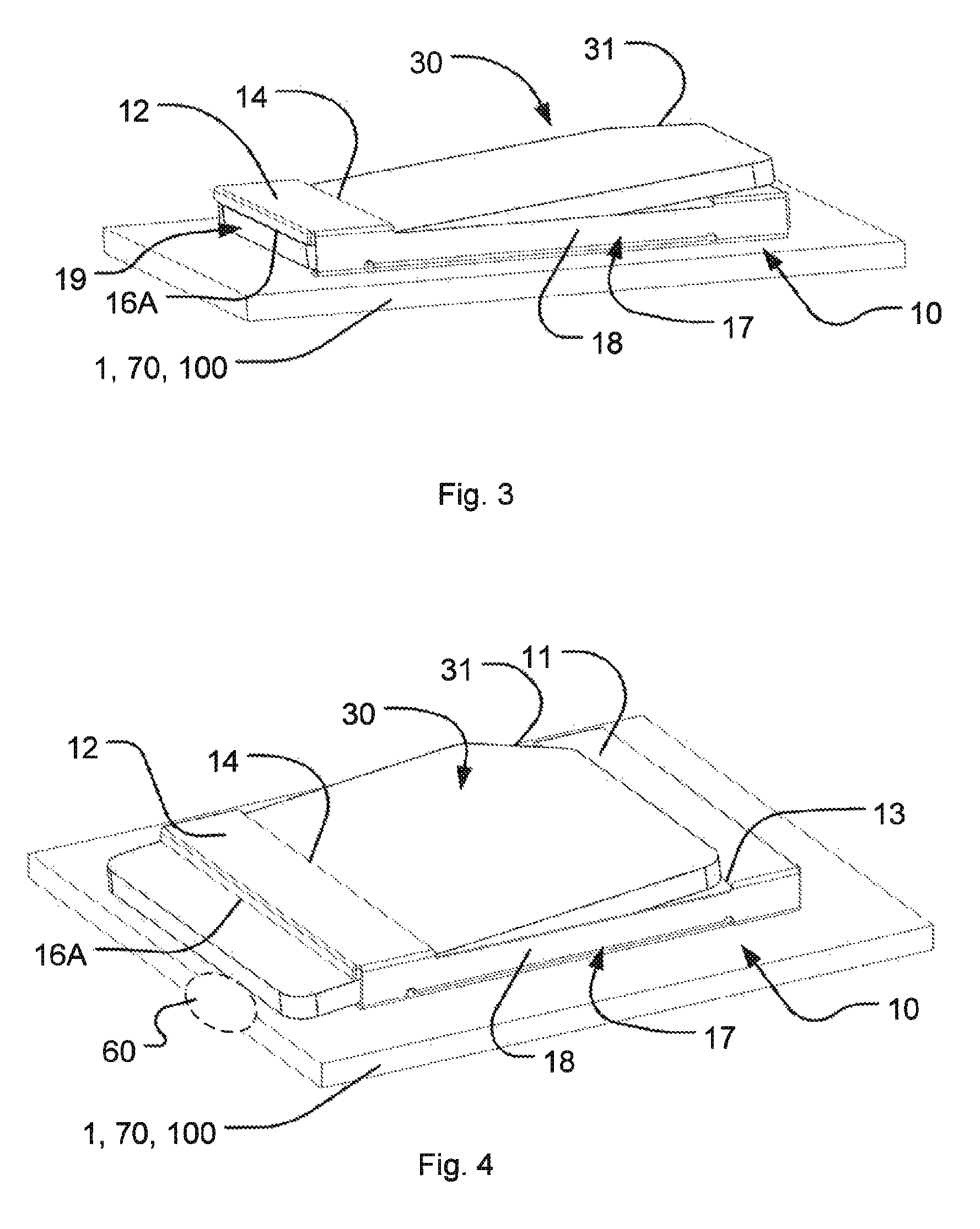
[0039]Aspects of the present invention will be described more fully hereinafter with reference to the accompanying drawings. FIGS. 1-15 show different views of a part of a portable electronic device 1 comprising a card holding device 10 according to different aspects of the invention. FIG. 16 shows a mobile electronic device 1, 100 where an exemplifying position of the card holding device 10 is outlined. This invention may, however, be embodied in many different forms and should not be construed as limited to the examples set forth herein. Rather, these examples are provided so that this disclosure will be thorough and complete, and will fully convey the scope of the invention to those skilled in the art. Like numbers refer to like elements throughout.

[0040]FIG. 16 shows a portable electronic / communication device 100, according to an embodiment of the present invention, comprising a casing 101, a display area 102 and means 104 for navigating among items (not shown) displayed in the ...


PUM


Abstract

A portable electronic device comprises a card holding device and a card reader for introducing and removing a card into and from the card reader in at least two different directions being angled in relation to each other during introduction and removal of the card.

Description

RELATED APPLICATIONS[0001]This application claims priority under 35 U.S.C. §119 based on U.S. Provisional Patent Application No. 61 / 657,249, filed Jun. 8, 2012, and European Patent Application No 12171340.8, filed Jun. 8, 2012, the disclosures of which are both hereby incorporated by reference herein.TECHNICAL FIELD OF THE INVENTION[0002]The present invention relates to a card connecting and holding device for facilitating removing / ejecting and / or introducing memory cards used in card readers, such as smart cards. The memory card holding and connecting device may advantageously be used in an electronic device having such a card reader.DESCRIPTION OF RELATED ART[0003]Today, there exist various ways of facilitating the introduction and removal, e.g., by ejection of external cards with memories used in portable electronic devices. Moreover, there exist different types of smart cards with differing sizes for different portable electronic devices, such as mobile telephones, smart phones,...

Claims


Application Information

Patent Timeline
Patent Type & Authority Patents(United States)
IPC IPC(8): G06K13/00G06K13/08G06K7/00H04B1/3816G06K13/14
CPCG06K7/003G06K13/085G06K13/14H04B1/3816H04M2250/14G06K7/0069G06K13/0806
Inventor KAZEMIFAR, OMIDSENDELIUS, PETERSKAGMO, DANIELWOLFF, MARTIN
Owner SONY CORP
Why Eureka
Try Eureka