Electrical connector used for transmitting high frequency signals

a technology of electrical connectors and high-frequency signals, applied in the direction of electrical discharge lamps, coupling device connections, coupling protection earth/shielding arrangements, etc., can solve the problems affecting the high-frequency performance of electrical connectors, and achieve the effect of improving high-frequency performan

Active Publication Date: 2016-04-12
HON HAI PRECISION IND CO LTD
View PDF17 Cites 55 Cited by
  • Summary
  • Abstract
  • Description
  • Claims
  • Application Information

AI Technical Summary

Benefits of technology

[0006]An object of the present invention is to provide an electrical connector which is conducive to improving high-frequency performance.

Problems solved by technology

However, there are some problems of signal transmission, such as signal interference between the terminals, and these problems will affect the high frequency performance of the electrical connector.

Method used


Image

  • Electrical connector used for transmitting high frequency signals
  • Electrical connector used for transmitting high frequency signals
  • Electrical connector used for transmitting high frequency signals

Examples


Embodiment Construction

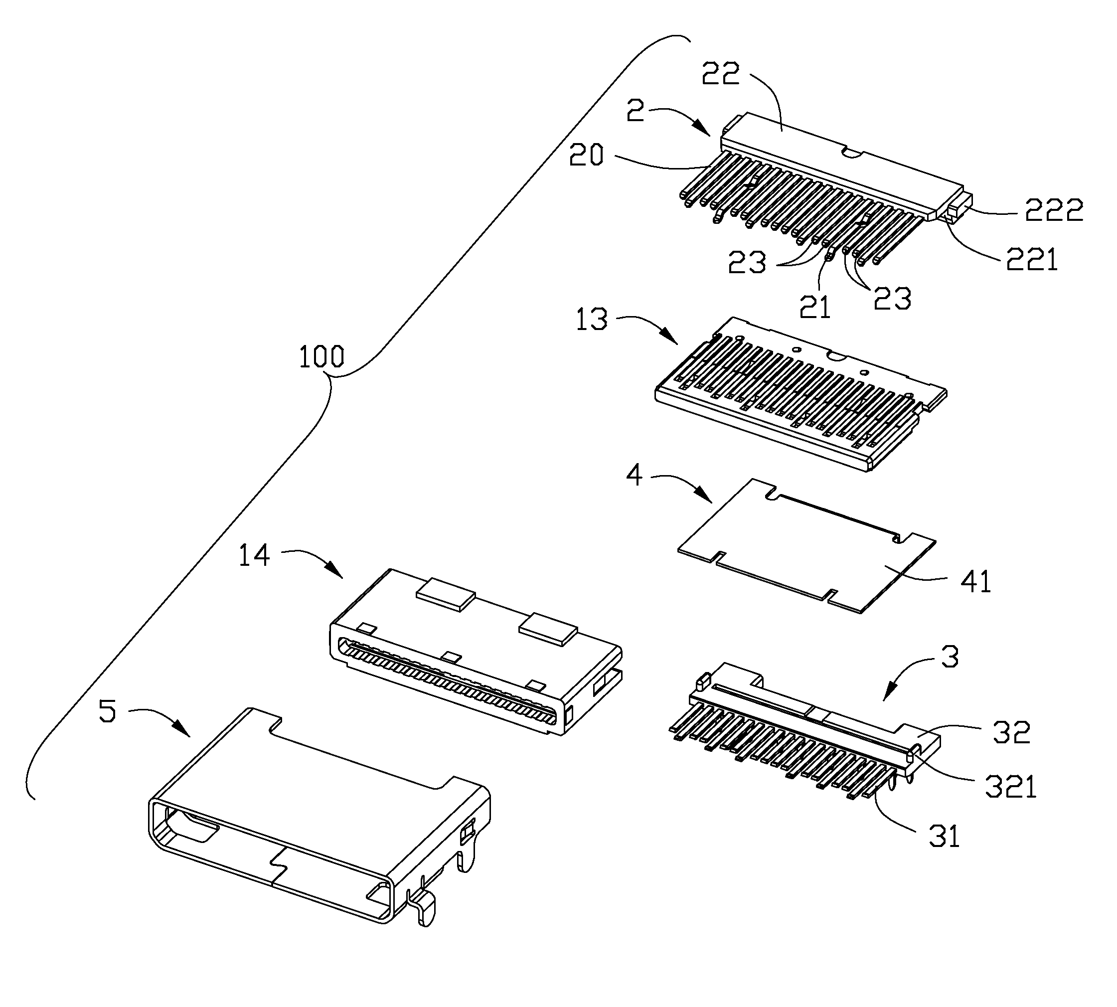
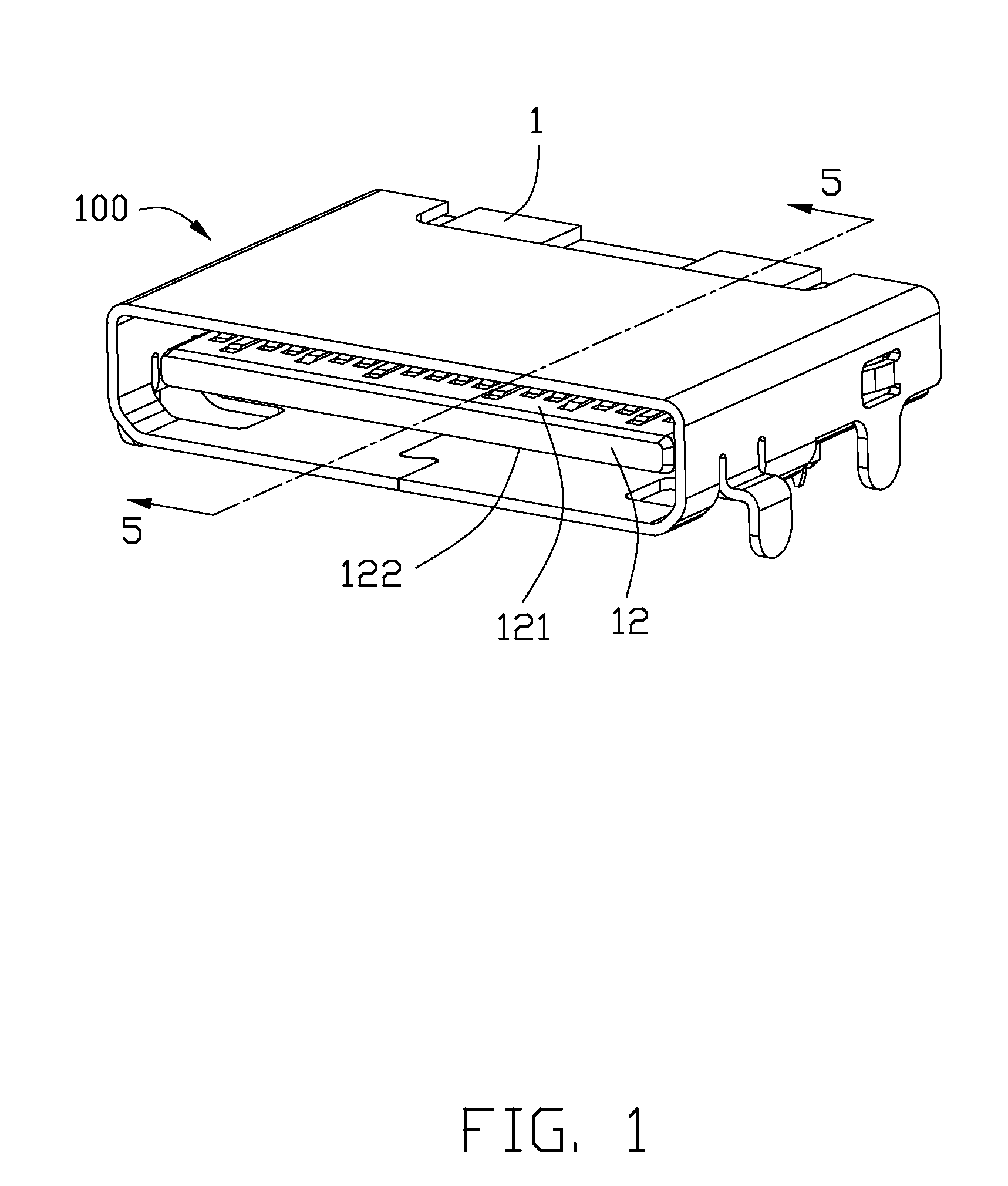
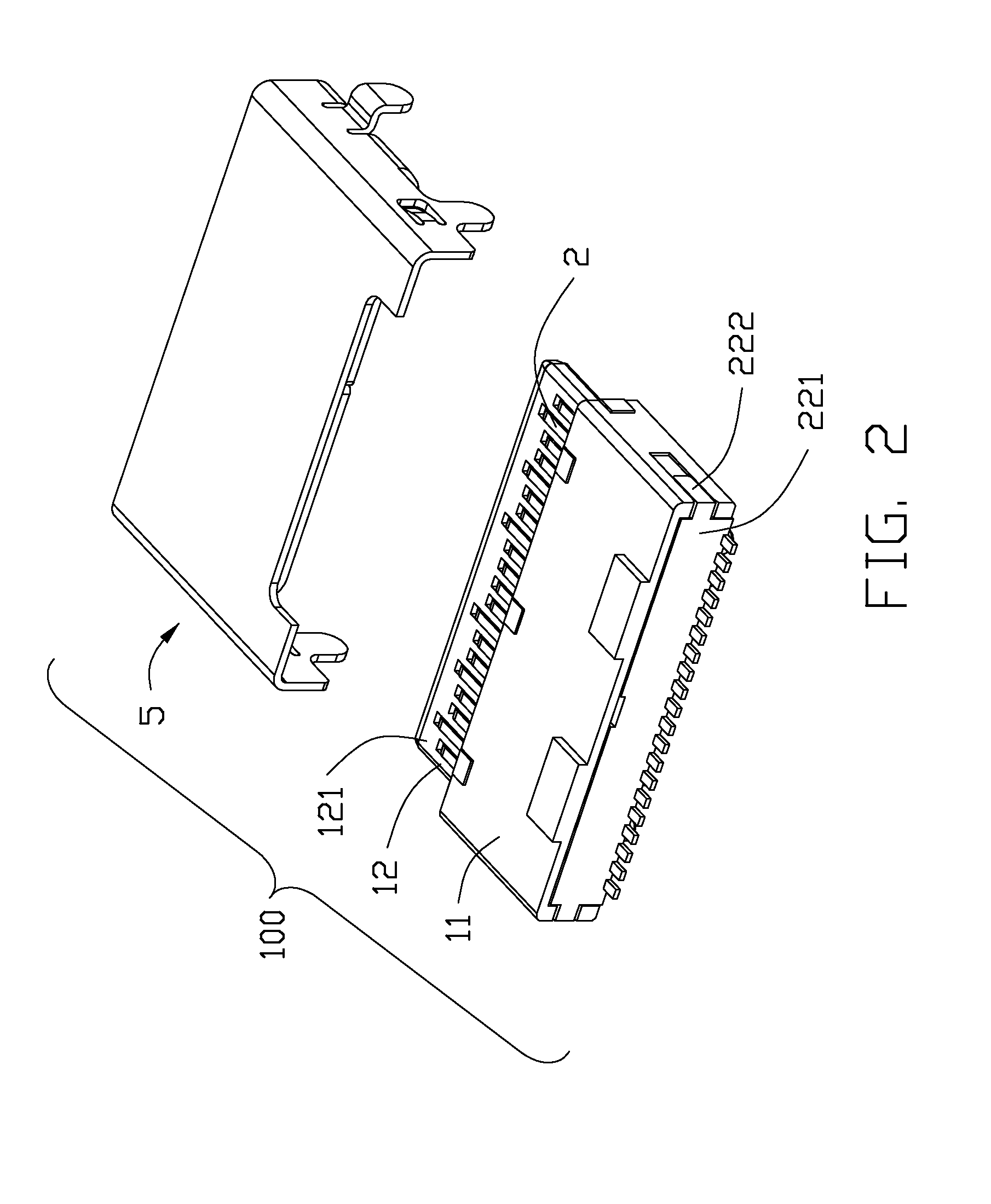
[0015]Reference will now be made to the drawing figures to describe a preferred embodiment of the present invention in detail. Referring to FIG. 1 to FIG. 3, an electrical connector 100 includes an insulative housing 1, a first terminal module 2 and a second terminal module 3 retained in the insulative housing 1, a shielding member 4 embedded in the insulative housing 1 and a metallic shell 5 surrounding the insulative housing 1. The insulative housing 1 defines a base portion 11 and a tongue portion 12 extending forwardly from the base portion 11, the tongue portion 12 defines a first surface 121 and a second surface 122 disposed oppositely. The first terminal module 2 is disposed on the first surface 121, the second terminal module 3 is disposed on the second surface 122 and the shielding member 4 is disposed in the tongue portion and located between the first and second surfaces, the first terminal module 2 includes two grounding contacts 21 and the grounding contact 21 defines a...


PUM


Abstract

An electrical connector includes an insulative housing defining a base portion and a tongue portion extending forwardly from the base portion, the tongue portion defines a first surface and a second surface disposed oppositely. A first terminal module is retained in the insulative housing and exposed on the first surface. And a shielding member is embedded in the tongue portion of the insulative housing and located between the first surface and the second surface. The first terminal module defines at least one grounding contact, the grounding contact defines a connecting portion projecting toward and contacting with the shielding member.

Description

BACKGROUND OF THE INVENTION[0001]1. Field of the Invention[0002]The present invention relates to an electrical connector, and more particularly to an electrical connector used for transmitting high-frequency signals.[0003]2. Description of the Related Art[0004]With the social development, it is a trend for a high-speed signal transmission and the electrical connectors are being developed with the high-speed signal transmission. However, there are some problems of signal transmission, such as signal interference between the terminals, and these problems will affect the high frequency performance of the electrical connector.[0005]Therefore, an improved electrical connector is highly desired to meet overcome the requirement.BRIEF SUMMARY OF THE INVENTION[0006]An object of the present invention is to provide an electrical connector which is conducive to improving high-frequency performance.[0007]In order to achieve above-mentioned object, an electrical connector includes an insulative h...

Claims


Application Information

Patent Timeline
Patent Type & Authority Patents(United States)
IPC IPC(8): H01R24/00H01R13/6585H01R13/648H01R33/00H01R13/6597H01R13/506H01R13/6594H01R107/00
CPCH01R13/6585H01R13/506H01R13/6594H01R13/6597H01R2107/00
Inventor WANG, QIANGZHANG, LIU-TAO
Owner HON HAI PRECISION IND CO LTD
Why Eureka
Try Eureka