Grease pump unit

a technology of grease pump and grease, which is applied in the direction of liquid transfer device, distribution equipment, transportation and packaging, etc., can solve the problems of minute bubbles in the grease to be agglomerated into large-diameter bubbles, failure of unmaintained stable lubricating performance of machinery, and change in quality of grease therein, etc., to suppress oil separation of grease, improve the effect of efficiency and simple structur

Active Publication Date: 2016-04-19
IHI ROTATING MACHINERY ENG CO LTD +1
View PDF8 Cites 14 Cited by
  • Summary
  • Abstract
  • Description
  • Claims
  • Application Information

AI Technical Summary

Benefits of technology

[0019]A grease pump unit of the invention can exhibit excellent effects. Grease in a grease can on a pedestal is sucked through a suction tube of a vertically moving pump device into a bubble dividing device where bubbles in the grease are micronized, the grease with bubbles thus micronized being supplied to a metering valve; thus, with the simple structure, prevented is a problem of the grease with the large-diameter bubbles being supplied to the metering valve. A portion of the grease not discharged through the metering valve is returned by the return pipe through the follower plate into the grease can; thus, the grease in all the supply pipe is circulated without stagnancy even if the metering valve is stopped and the oil separation of the grease is suppressed.

Problems solved by technology

However, the suction of the grease in the grease can by the suction unit may cause minute bubbles intermingling in the grease to be agglomerated into large-diameter bubbles.
Such large-diameter bubbles supplied to the metering valve may disadvantageously make the grease supply intermittent by the metering valve to the machinery and equipment at the oiling site, resulting in serious failure of unmaintained stable lubricating performance to the machinery and equipment which are required to be always volumetrically supplied with the grease in a minute amount.
There is also a problem that, after the grease can is opened, the grease therein is changed in quality by oxidization through contact with ambient air and oil separation through gravity.

Method used


Image

  • Grease pump unit
  • Grease pump unit
  • Grease pump unit

Examples


Embodiment Construction

[0041]An embodiment of a grease pump unit according to the invention will be described in conjunction with the drawings.

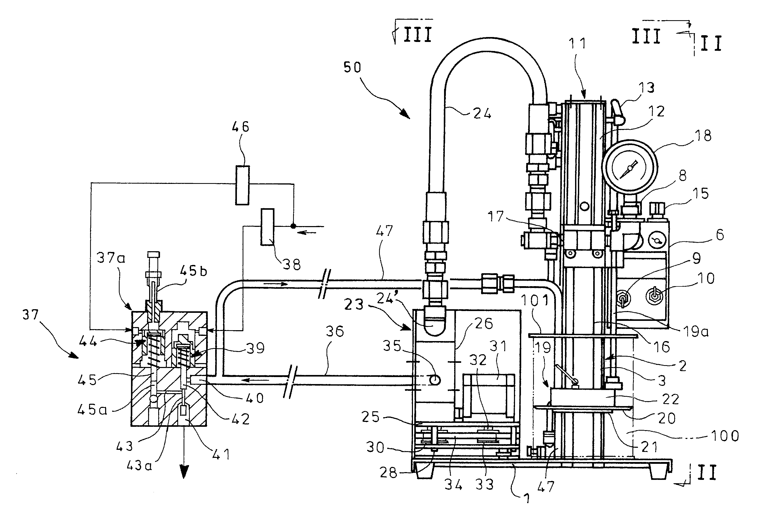
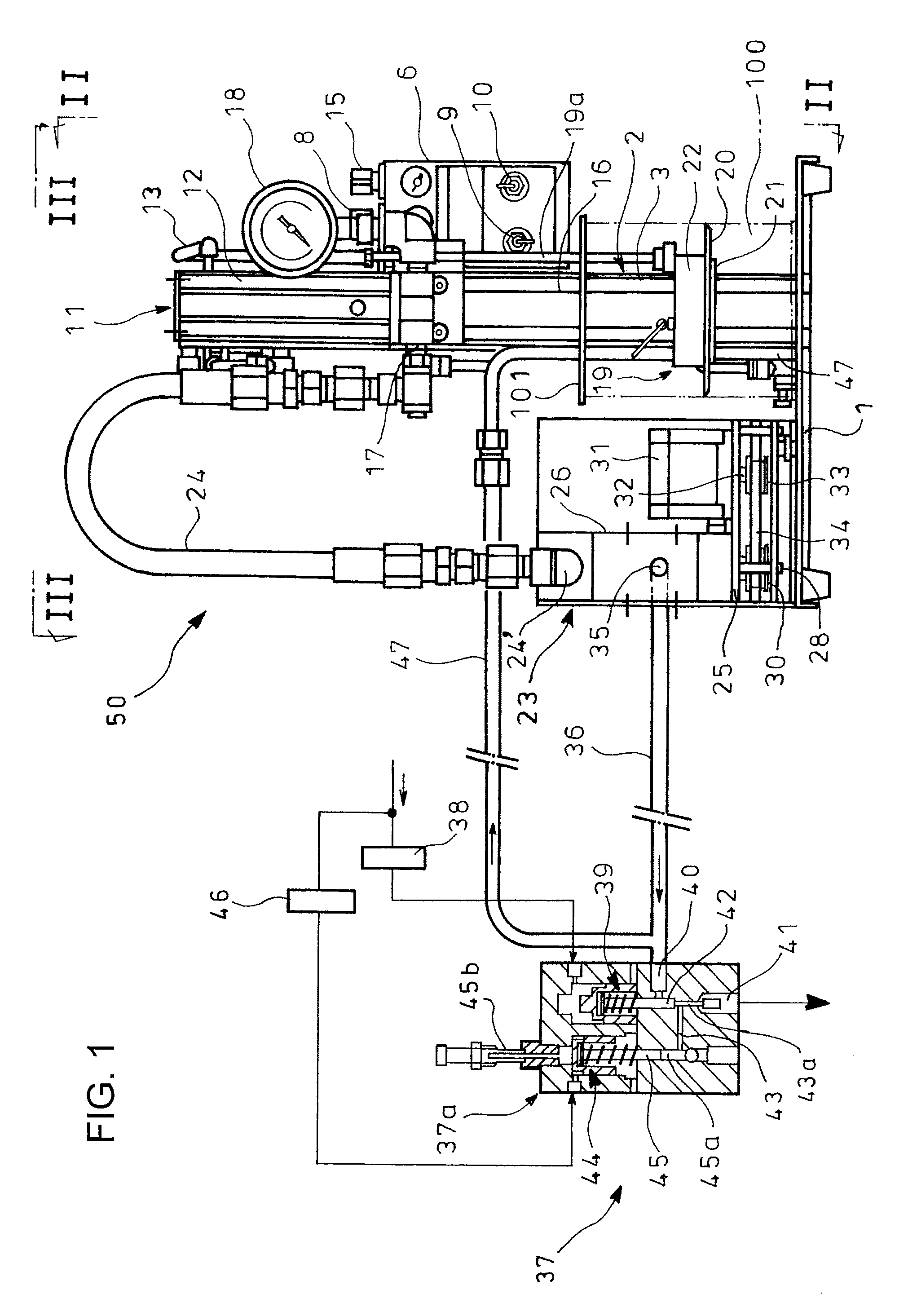
[0042]FIG. 1 is an overall front view showing the embodiment of the grease pump unit according to the invention. FIG. 2 is a side view looking in a direction of arrows II in FIG. 1. FIG. 3 is a plan view looking in a direction of arrows III in FIG. 1. The grease pump unit comprises a grease supplying device 50 and a metering valve 37.

[0043]The grease supplying device 50 has a pedestal 1 on which a grease can 100 is installed, and a lifer 2 stands on a back side of the pedestal 1. The lifter 2 illustrated is an air cylinder 3. The air cylinder 3 has an upwardly protruding cylinder rod 4 with an upper end to which secured is a vertically movable member 5 in the form of an L-shaped plate. The cylinder rod 4 of the air cylinder 3 is driven into protrusion and retraction with compressed air supplied through an air pipe 7 (FIG. 3) connected to an operation panel 6 arrang...


PUM


Abstract

A grease pump unit has a metering valve 37 and a grease supplying device 50 in which a suction tube 16 on a pump device 11 extends through a follower plate 19 in a grease can 100, grease in the grease can 100 being sucked through the suction tube 16 and discharged through a discharge port 17 by activation of the pump device 11. Provided are a bubble dividing device 32 which supplies the grease discharged through the discharge port 17 through an supply pipe 24 to micronize bubbles in the grease and which supplies the grease through a supply pipe 36 to the metering valve 37, and a return pipe 47 which returns a portion of the grease not discharged through the metering valve 37 into the grease can 100 via the follower plate 19.

Description

TECHNICAL FIELD[0001]The present invention relates to a grease pump unit which can supply grease in a grease can to a metering valve at an oiling site with bubbles in the grease being micronized, and can return a portion of the grease not consumed by the metering valve into the grease can for circulation to suppress oil separation in the grease.BACKGROUND ART[0002]Conventionally used is a lubricating pump installed on a grease can to supply grease in the grease can to a metering valve or the like on machinery and equipment at an oiling site (see Patent Literature 1).[0003]In the lubricating pump of the Patent Literature 1, a lid on which a suction unit is integrally arranged can be placed on a grease can to close an opening of the can. A suction pipe extends downward from the lid and is in communication with the suction unit. A follower plate is vertically movably suspended by ball chains from the suction pipe, has a central through bore through which the suction pipe fittingly exte...

Claims


Application Information

Patent Timeline
Patent Type & Authority Patents(United States)
IPC IPC(8): B67D7/36F16N25/00F16N11/10F16N7/38B67D7/04
CPCB67D7/04F16N7/385F16N11/10F16N25/00Y10T137/2931
Inventor DOI, HIROYUKITANAKA, HIROKAZU
Owner IHI ROTATING MACHINERY ENG CO LTD
Why Eureka
Try Eureka