Magnetic sensor device

a magnetic sensor and sensor technology, applied in the field of magnetic sensor devices, can solve the problems of inability to process high-speed signals, noise generated in magnetic sensor devices, and low signal processing efficiency, and achieve the effect of high speed

Active Publication Date: 2016-04-26
ABLIC INC
View PDF2 Cites 0 Cited by
  • Summary
  • Abstract
  • Description
  • Claims
  • Application Information

AI Technical Summary

Benefits of technology

[0011]It is an object of the present invention to provide a magnetic sensor device which utilizes a comparator including a plurality of Hall elements and a plurality of differential input pairs to cancel out offset components of the Hall elements, thereby realizing a highly accurate magnetic field intensity detection, and at the same time, performing high speed signal processing.
[0014]According to the magnetic sensor device of one embodiment of the present invention, the detection voltage level of the magnetic field intensity can be arbitrarily set by a small scale circuit, and thus, the Hall element offset can be cancelled out, and at the same time, the signal processing can be performed at high speed.

Problems solved by technology

An output voltage of a magnetoelectric converting element is minute, and thus, an offset voltage of the magnetoelectric converting element (element offset voltage), an offset voltage of the amplifier or the comparator (input offset voltage), or noise generated in the magnetic sensor device becomes a problem.
The noise is generated mainly by flicker noise of a single transistor which forms a circuit or thermal noise of a single transistor or a resistance element.
However, in the related-art magnetic sensor device, time-division operation in which a plurality of signal processing periods such as a sample phase and a comparison phase is necessary to be provided for the purpose of cancelling out offset components, which is inappropriate for high speed signal processing.
Further, the time-division operation requires connection of a switch circuit and a capacitor element, which complicates the circuit configuration.

Method used


Image

  • Magnetic sensor device
  • Magnetic sensor device
  • Magnetic sensor device

Examples


Embodiment Construction

[0021]An embodiment of the present invention is described in detail in the following with reference to the attached drawings. A magnetic sensor device according to the present invention is widely used as a sensor for detecting the state of a magnetic field intensity, for example, a sensor for detecting an open / close state in a folder-type cellular phone, a notebook computer, or the like or a sensor for detecting a rotational position of a motor. In the following embodiment, a magnetic sensor device using Hall elements is described, but the magnetic sensor device according to the present invention may use, instead of a Hall element which outputs a voltage in accordance with a magnetic field intensity, a converting element which similarly outputs a voltage in accordance with a physical quantity such as acceleration or a pressure.

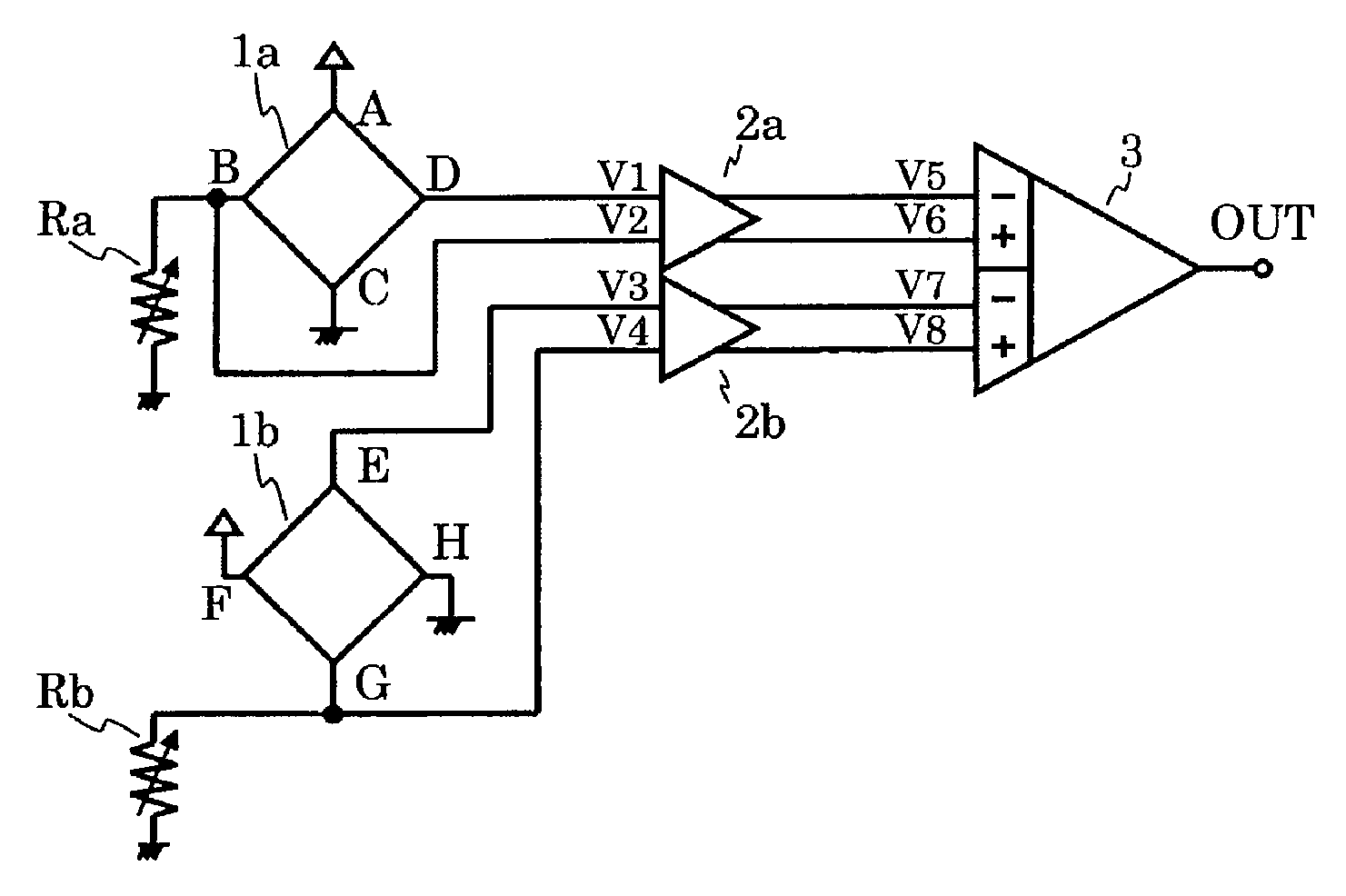
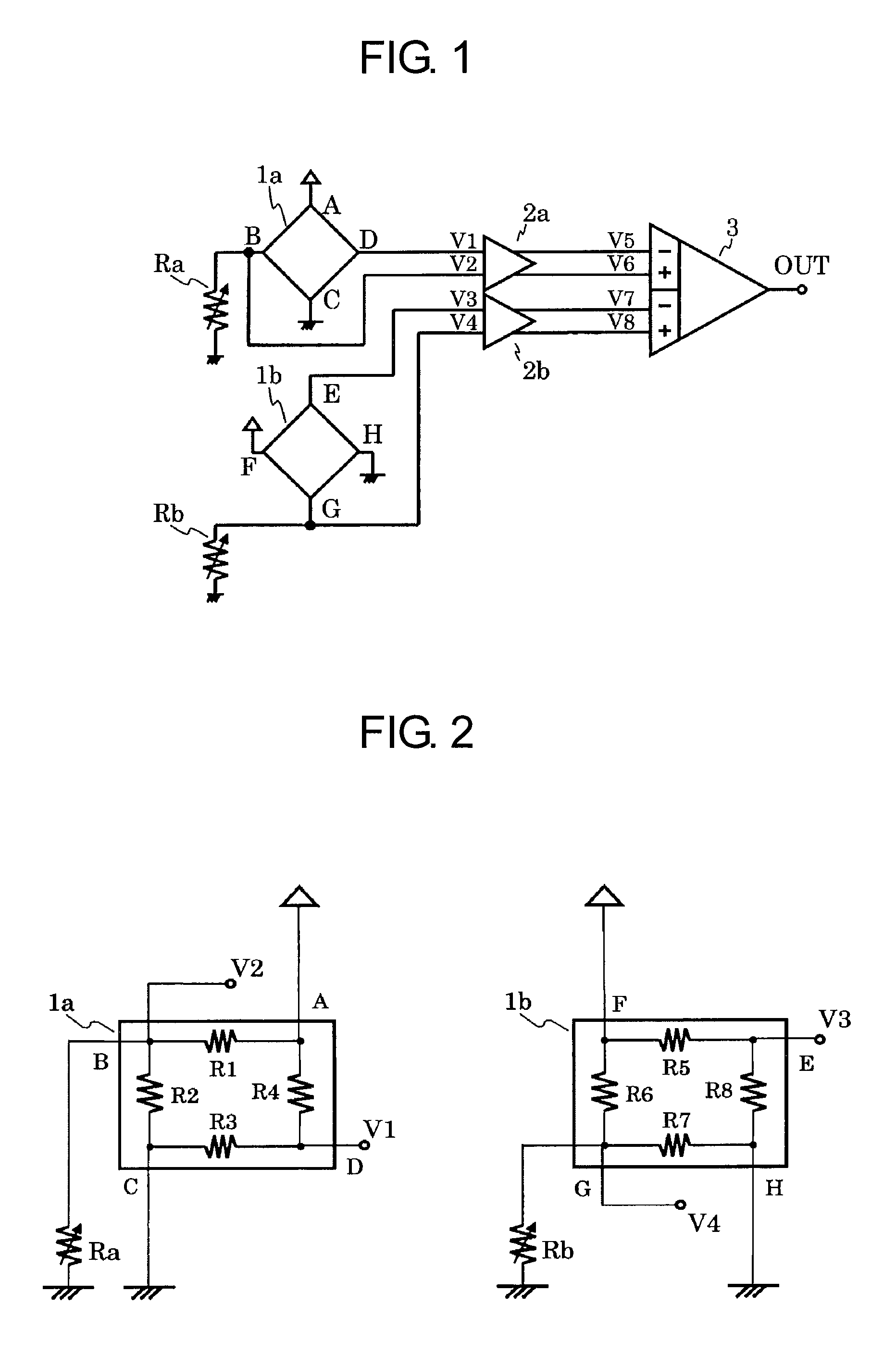
[0022]FIG. 1 is a circuit diagram illustrating the magnetic sensor device according to this embodiment. The magnetic sensor device according to this embodimen...


PUM


Abstract

Provided is a magnetic sensor device capable of performing signal processing at high speed with high accuracy. The magnetic sensor device includes: a plurality of Hall elements; a plurality of differential amplifiers to which the plurality of Hall elements are connected, respectively; a detection voltage setting circuit for outputting a reference voltage; and a comparator including: a plurality of differential input pairs connected to the plurality of differential amplifiers, respectively; and a differential input pair connected to the detection voltage setting circuit.

Description

RELATED APPLICATIONS[0001]This application claims priority under 35 U.S.C. §119 to Japanese Patent Application No. 2013-032117 filed on Feb. 21, 2013, the entire content of which is hereby incorporated by reference.BACKGROUND OF THE INVENTION[0002]1. Field of the Invention[0003]The present invention relates to a magnetic sensor device which converts a magnetic field intensity into an electric signal, and, for example, relates to a magnetic sensor device used as a sensor for detecting an open / close state of a folder-type cellular phone, a notebook computer, or the like or a sensor for detecting a rotational position of a motor.[0004]2. Description of the Related Art[0005]As a sensor for detecting an open / close state in a folder-type cellular phone, a notebook computer, or the like or a sensor for detecting a rotational position of a motor, a magnetic sensor device is used.[0006]A magnetic sensor device outputs a voltage in proportion to a magnetic field intensity or a magnetic flux d...

Claims


Application Information

Patent Timeline
Patent Type & Authority Patents(United States)
IPC IPC(8): G01R33/07G01D5/14H03K17/95G01R33/00
CPCG01D5/145G01R33/0029G01R33/07H03K17/9517
Inventor MURAOKA, DAISUKEARIYAMA, MINORU
Owner ABLIC INC
Why Eureka
Try Eureka