Advanced speculum

a technology of speculum and speculum, applied in the field of advanced speculum, can solve the problems of increasing the exposure of the thin blade edge, affecting the function of the patient, affecting the patient's recovery, etc., and achieves the effects of less elastic, and reducing the risk of injury

Active Publication Date: 2016-05-03
BRIDEA IP
View PDF8 Cites 3 Cited by
  • Summary
  • Abstract
  • Description
  • Claims
  • Application Information

AI Technical Summary

Benefits of technology

[0008]The tissue lining the vaginal wall is only partially elastic and becomes less elastic over time. When inserting, rotating, opening and closing the speculum these edges come in direct contact with the lining of the vagina. During insertion of the speculum, muscle tissue of the vagina around the speculum is widened. The tissue lining the vaginal wall is thereby squeezed against the speculum. As the speculum is inserted the beaks are most commonly also rotated from a nearly vertical or 5 minutes past 7 orientation to a horizontal or quarter past 9 position as defined by the motion of fingers of a clock. There is generally a gap between the blades, thereby exposing at least part of the blade edges. Due to the rotating action of the speculum the blades, also called beak parts can become misaligned. This further increases the exposure of the thin blade edges. These thin edges scrape against the vaginal lining and in some instances can cause severe discomfort, distress and injury.
[0009]When a speculum is inserted the pivotable blades are subsequently at least partially distended or opened. Due to the constricting function of the vaginal muscle tissue around the speculum, lack of elasticity of the skin tissue lining the vagina wall and gravity tissue often tends to protrude basically into the space defined by the beak parts, thereby folding around the edges. The relatively thin edges can cause discomfort by allowing the tissue to make a sharp fold over these edges. This also causes localized pressure in the skin to build up over the narrow edges. This can limit blood flow and cause injury at prolonged exposure.
[0015]This invention seeks to provide a surgical instrument which is reusable, is lightweight, but nevertheless shows sufficient overall strength, without resulting in discomforts normally associated with in particular moulded speculum instruments.

Problems solved by technology

The inventor came to the realization that edges of the beaks can cause discomfort and injury to the patient in particular if the parting line which is associated with a moulding method is not properly positioned on the beak or blade edge, in particular its edge face.
This further increases the exposure of the thin blade edges.
These thin edges scrape against the vaginal lining and in some instances can cause severe discomfort, distress and injury.
Due to the constricting function of the vaginal muscle tissue around the speculum, lack of elasticity of the skin tissue lining the vagina wall and gravity tissue often tends to protrude basically into the space defined by the beak parts, thereby folding around the edges.
The relatively thin edges can cause discomfort by allowing the tissue to make a sharp fold over these edges.
This also causes localized pressure in the skin to build up over the narrow edges.
This can limit blood flow and cause injury at prolonged exposure.
When the Cervix protrudes in between the distal ends of the blades or is held by their ends the thin edge at the end of one or more of the beak parts can also cause discomfort or injury as previously described for the side edges.
Additionally, when the beak parts are used to move, lift, hold, grasp or otherwise manipulate the Cervix the edge comes in direct contact with the Cervix and can cause extra discomfort or injury due to the pressures being highly localized on the thin edges.

Method used


Image

  • Advanced speculum
  • Advanced speculum
  • Advanced speculum

Examples


Embodiment Construction

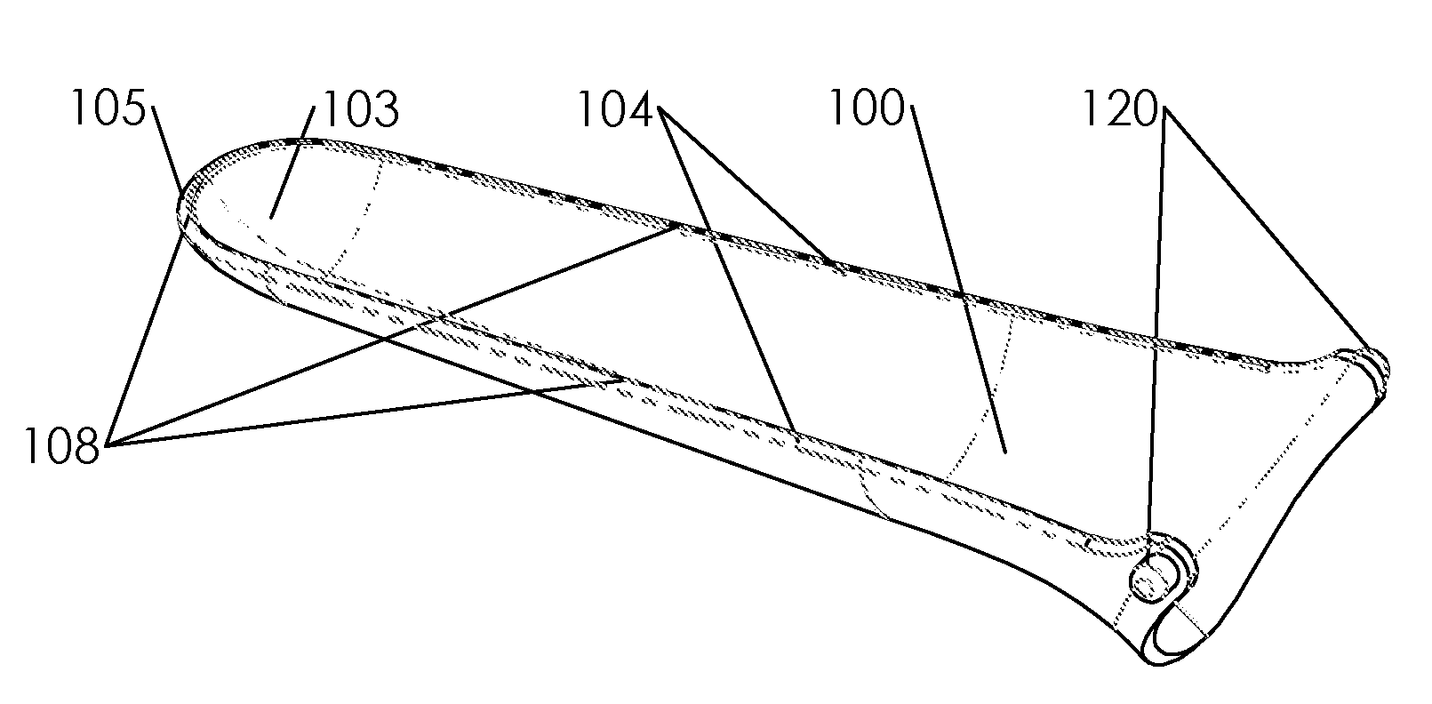
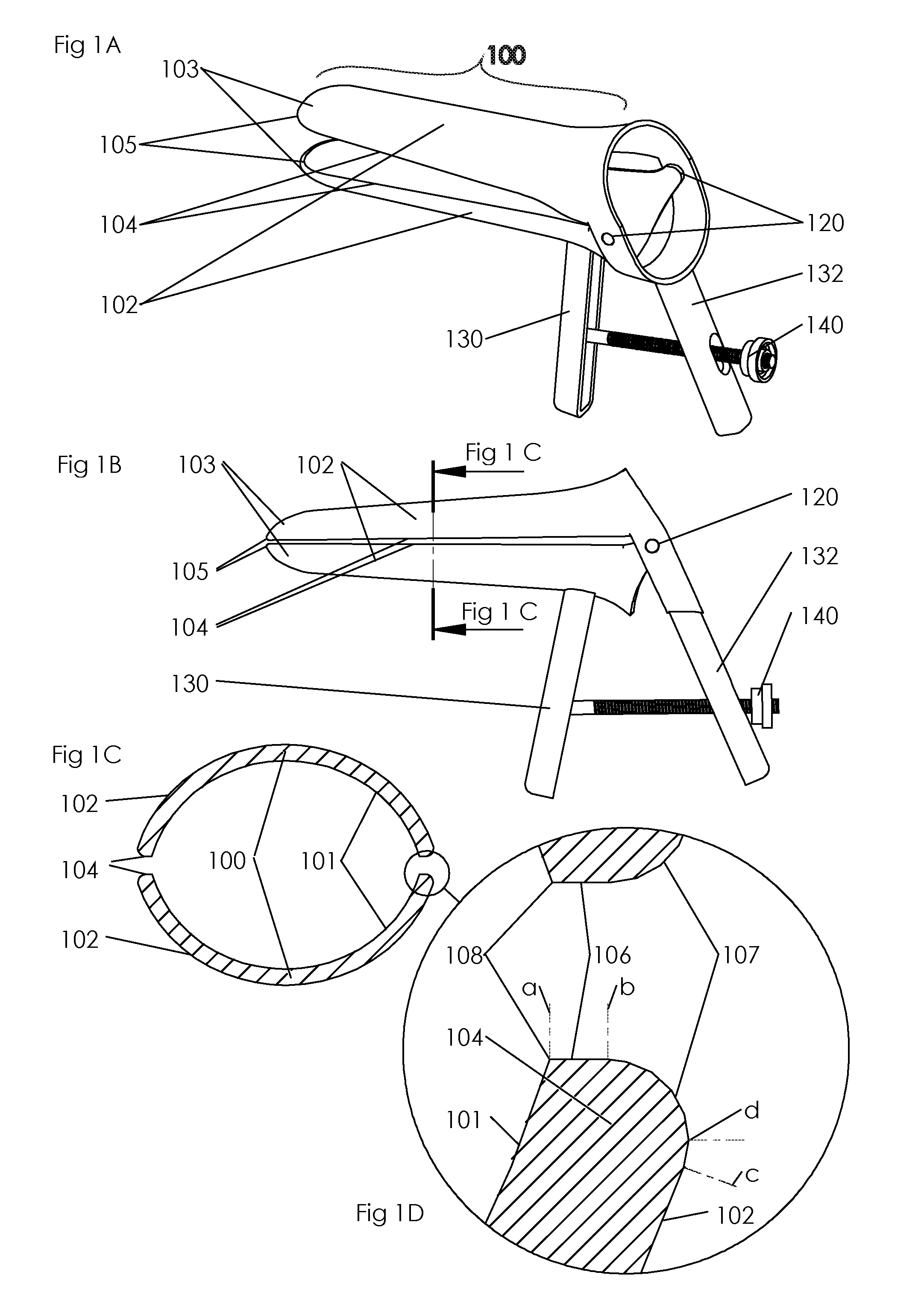
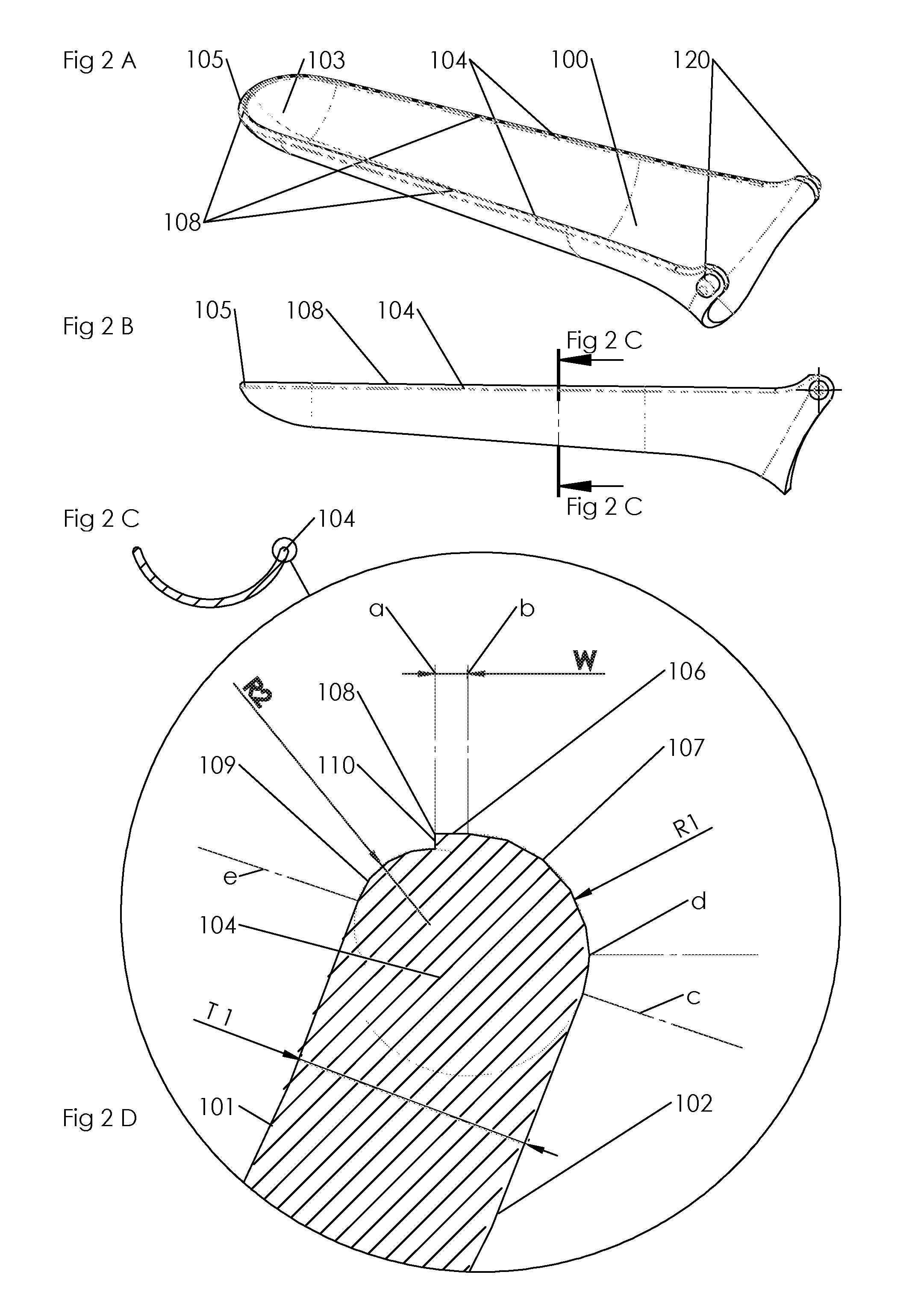
[0035]FIGS. 1A and 1B depict an embodiment of a commonly used Vaginal Speculum according to prior art, comprising blades or Beak Parts 100, with an Inner Surface 101 and an Outer Surface 102. The Beak Parts 100 have Beak Edges 104 and have Cupped Ends 103 at their respective distal ends. Cup Edges 105 form the edges of the Cupped Ends 103. The Beak Parts 100 are inserted into the vagina in a closed state with the Cupped Ends 103 initiating penetration. Hence the Cupped Ends are referred to as the distal end of the Beak Parts 100 in this application. The Beak Parts are typically coupled in such a way that they can move away from each other or towards each other in an angular or a lateral movement, or a combination of both, to expose part of the interior of the vaginal cavity.

[0036]Typically the common speculum has a Pivoting Joint 120 at the proximal ends of the Beak Parts 100. Once Beak Parts are inserted into the vaginal cavity the First Handle 130, and Second Handle 132 are moved ...


PUM


Abstract

It is described a surgical instrument such as a speculum comprising longitudinally extending cups-shaped pivotably mounted blades manufactured from a moldable material, such as plastic or metal. Each blade has an inwardly curved circumferential edge with an edge face which is provided with a parting line resulting from molding the blades. Negative effects such as possible injuries associated with parting lines or steps can be mitigated by inwardly relocating these lines on an edge face of the inwardly curved circumferential edge.

Description

CROSS-REFERENCE TO RELATED APPLICATIONS[0001]This Application is a National Stage of International Application No. PCT / NL2012 / 050235 filed Apr. 6, 2012, the contents of which is incorporated by reference herein.BACKGROUND[0002]A speculum is a commonly-used device for opening or distending an orifice or cavity of a body or incision in a body to permit examination of the interior and / or to enable a procedure among which the taking of a sample or treatment of the inspected area.[0003]The basic function of a speculum is to increase the size or diameter of this, orifice, cavity or incision by increasing the distance between two or more surfaces or parts of surfaces of the speculum. The force required for this handling can be supplied manually such as by the squeezing together of two handles. Said force can be applied direct or relayed through technical solutions for example by means of wires, cables and or rods. Said force can also be supplied or relayed electrically, pneumatically or vi...

Claims


Application Information

Patent Timeline
Patent Type & Authority Patents(United States)
IPC IPC(8): A61B1/32
CPCA61B1/32
Inventor ROELOFFS, BOB
Owner BRIDEA IP
Why Eureka
Try Eureka