Load bearing surface

a technology of load bearings and components, applied in the direction of sofas, beds, chairs, etc., can solve the problems of inability to tune the characteristics of conventional molded seats, uncomfortable and sometimes ergonomically unacceptable load bearing surfaces, and typically do not provide the level of support and comfort available in more expensive load bearing surfaces, etc., to achieve convenient and efficient manufacturing.

Active Publication Date: 2010-09-30
ILLINOIS TOOL WORKS INC
View PDF12 Cites 2 Cited by
  • Summary
  • Abstract
  • Description
  • Claims
  • Application Information

AI Technical Summary

Benefits of technology

[0012]The present invention provides a comfortable, durable load bearing surface that it easily secured to a support structure. The molded elastomeric membrane is efficient to manufacture, and the orientation of the crystalline structure of the molded part provides comfort control and durability. The attachment portions eliminate the need to separate fasteners or attachment features on the support structure. Other features and advantages of the invention will become apparent to those skilled in the art upon review of the following detailed description, claims and drawings in which like numerals are used to designate like features.

Problems solved by technology

Although these molded chairs provide an inexpensive seating option, they typically do not provide the level of support and comfort available in more expensive load bearing surfaces, such as conventional cushion sets.
In seating and other body-support applications, this may result in an uncomfortable and sometimes ergonomically unacceptable load bearing surface.
Further, the ability to tune the characteristics of a conventional molded seat is relatively limited.
Different materials and different material thicknesses can be used to provide a limited degree of control over the characteristics of the seat, but this level of control is not sufficient in many applications.
In many cases, materials that are thick enough to provide the necessary support are too rigid and uncomfortable, and thinner plastic surfaces, such as membranes or woven plastic fibers tend to permanently deform (or creep) over time.
Of course, screws and other separate fasteners can be used, but they are known to be problematic because of the extra costs associated with additional materials and manufacturing steps, and because they tend to be unattractive.
Although generally acceptable, these methods can be problematic in situations where the features of the support frame cannot be manipulated as necessary to accommodate or receive attachment features on the load bearing surface.
For instance, it can be difficult and costly to create a steel support frame with a plurality of properly spaced apart protrusions extending from it to attach to a load bearing surface.

Method used


Image

  • Load bearing surface
  • Load bearing surface
  • Load bearing surface

Examples


Embodiment Construction

[0020]I. Overview

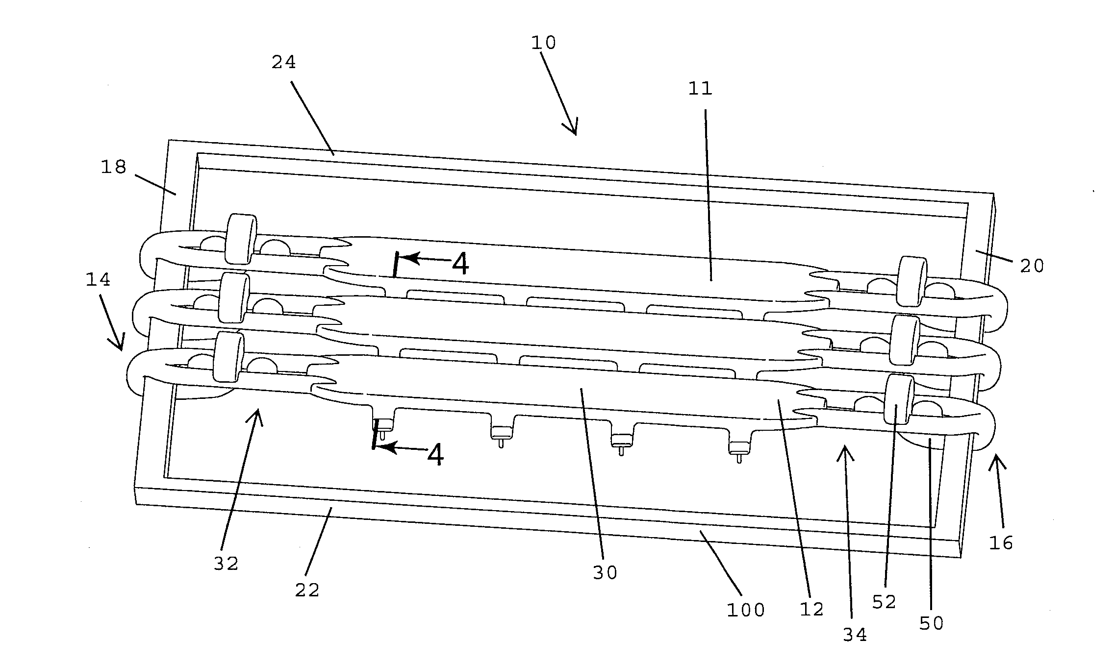
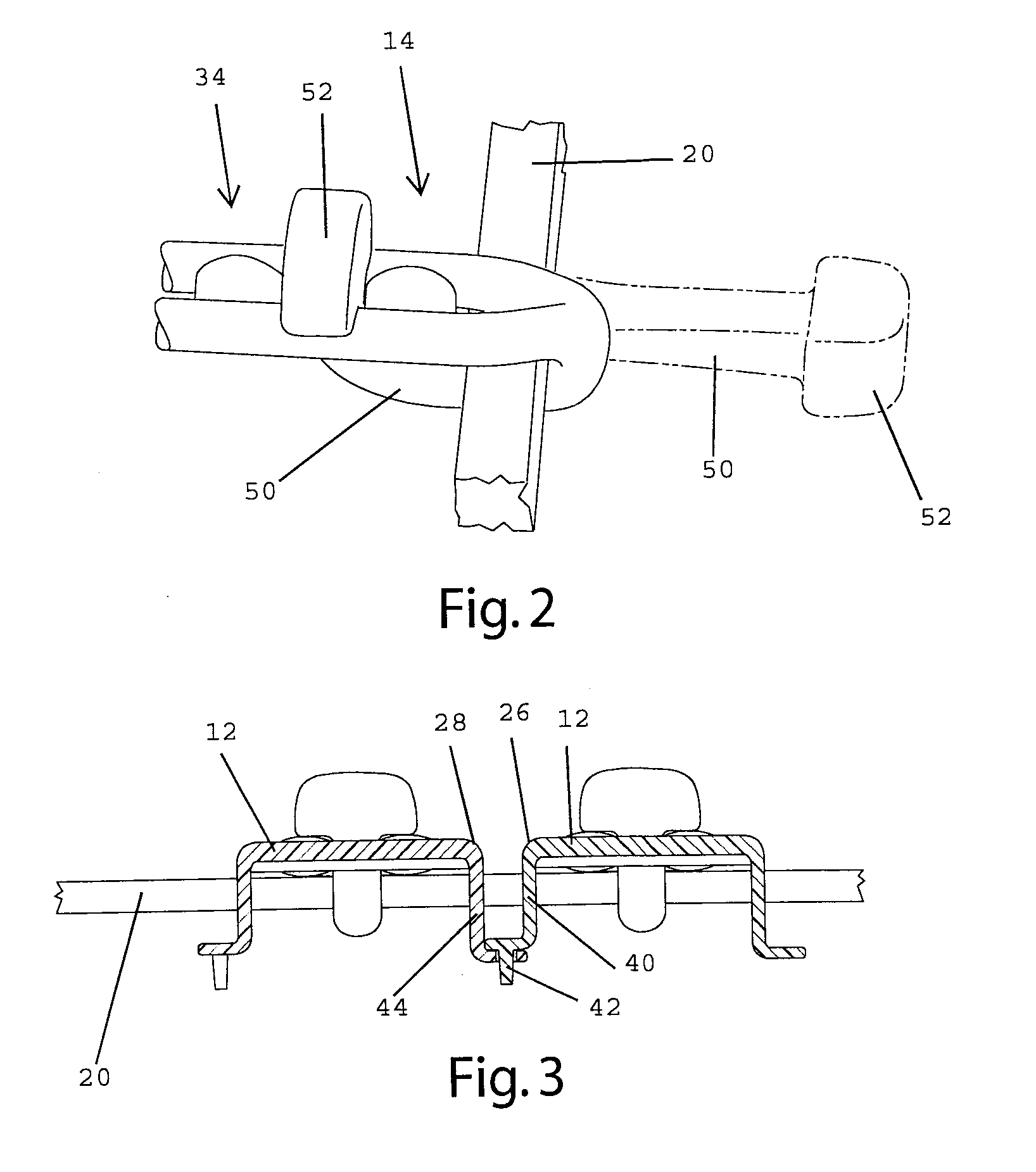
[0021]A load bearing surface according to one embodiment of the present invention is shown in FIG. 1 and generally designated 10. The load bearing surface 10 shown in FIG. 1 is a molded membrane 11 that may be suspended from a support structure, such as a chair seat frame 100. In the illustrated embodiment, the membrane 11 is formed from a plurality of adjacent molded elastomeric strips 12. Each elastomeric strip includes first 14 and second 16 ends that wrap around frame members 18, 20 of the support structure 100 and attach to the strip itself to secure the strip to the support structure 100. The embodiment shown in FIG. 1 includes a portion of the load bearing surface 10, extending over a portion of a seat frame support structure 100. In one embodiment, the complete load bearing surface 10 for a seat frame 100 includes fourteen adjacent strips 12 extending over the entire seat frame 100, but the number of strips may vary from application to application. By way of...


PUM

PropertyMeasurementUnit
thicknessaaaaaaaaaa
crystalline structureaaaaaaaaaa
elasticaaaaaaaaaa

Abstract

An elastomeric load bearing surface includes an integral attachment mechanism, wherein portions of the load bearing surface attach to each other to secure the load bearing surface to a support structure. In one embodiment, a molded elastomeric strip includes a tab that wraps around a support structure frame member, and a receptacle that receives and retains the first portion. The load bearing surface may be formed from a plurality of molded elastomeric strips, each having a tab extending around the frame member and an opening receiving the tab. The strips may be oriented to reduce creep by aligning the crystalline structure of the elastomer in one direction.

Description

CROSS REFERENCE TO RELATED APPLICATION[0001]This Non-Provisional Application claims benefit to U.S. Provisional Application Ser. No. 60 / 982,871, filed Oct. 26, 2007.FIELD OF THE INVENTION[0002]The present invention relates to load bearing assemblies, and more particularly to load bearing assemblies for supporting a load bearing surface over an opening with a peripheral frame, such as the seat or back of a chair or bench, or the support surface of a bed, cot or other similar product.BACKGROUND OF THE INVENTION[0003]There are continuing efforts to develop new and improved load bearing assemblies. In general, the primary objectives of these efforts are to obtain a durable and inexpensive load bearing surface that is relatively easy to manufacture. It is also important to address issues in the attachment of the load bearing surface to the support structure.[0004]It is known to provide molded load bearing surfaces for a wide variety of applications. For example, molded plastic chairs (e....

Claims


Application Information

Patent Timeline
Patent Type & Authority Applications(United States)
IPC IPC(8): F16M13/00B23P17/00
CPCA47C7/287A47C23/002Y10T29/4998A47C23/064A47C23/061
Inventor COFFIELD, TIMOTHY P.HARTMANN, ANDREW B.
Owner ILLINOIS TOOL WORKS INC
Why Eureka
Try Eureka