
A lighting device comprising a housing and a bag

Inactive Publication Date: 2021-02-04
SIGNIFY HLDG BV
View PDF0 Cites 3 Cited by
  • Summary
  • Abstract
  • Description
  • Claims
  • Application Information

AI Technical Summary

Benefits of technology

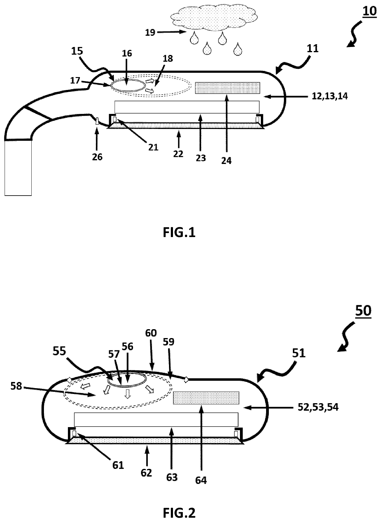
The invention is a bag designed to reduce the negative effects of pressure drop in a lighting device. The bag is filled with a fluid and is sealed with a gasproof material. It is isolated from the device's housing fluid so it does not experience pressure drop initially. When there is a sudden pressure drop in the housing fluid, the bag expands and reduces the volume of the housing, resulting in an increase in pressure. The bag material is designed to be flexible and does not create tension, allowing it to deform in areas between components and save space in the lighting device.

Problems solved by technology

This sudden pressure drop is undesired, because it not only puts mechanical stress on gaskets, seals, joints, and / or walls, but it also allows contaminants such as water, moisture, dust, dirt, insects, etc. to be sucked into the housing via leaks or apertures due to the resulting negative pressure gradient (i.e. pressure inside housing is lower than outside the housing).

Method used


Image

  • A lighting device comprising a housing and a bag
  • A lighting device comprising a housing and a bag
  • A lighting device comprising a housing and a bag

Examples


first embodiment

[0064]As mentioned, the present invention provides an improved lighting device 10. FIG. 1 depicts schematically a side view of a lighting device 10 according to the invention. The lighting device comprises a housing 11 and a bag 15. The housing 11 is made of metal. Alternatively, the housing may be made of, or partly made of, steel, aluminum, ceramic, polymer, fiber reinforced polymer, copper, or a combination thereof. The lighting device 10 further comprises a light source 23 for providing light through a light exit window 22, which is driven by a driver 24 and controlled by control electronics (not shown). Alternatively, other configuration of components may be present. The light source 23 is a LED light source, but may alternatively be a conventional light source. The window 22 is a transparent plate such as glass or polymer, but may alternatively comprise further optical features. The window 22 is gastightly sealed to the housing 11 by means of the gasket 21. The lighting device...

second embodiment

[0076]FIG. 2 depicts schematically a top view of a lighting device 50 comprising a housing 51 and a bag 55; which is partly similar to the embodiment depicted in FIG. 1, but now wherein the lighting device 50 is a flood light for illuminating a large stadium area and wherein the housing 51 comprises a panel 60 for closing an aperture 59 of the housing 51.

[0077]Referring to FIG. 2, the lighting device 50 comprises a housing 51 made of fiber reinforced polymer material, such that the lighting device 50 is lightweight, but still able to cope with mechanical loads and / or heat transfer from its interior to its exterior. The lighting device 50 further comprises a light source 53 for providing light through an optical element being a lens plate 62. The lens plate 62 is gastightly sealed to the housing 51 by means of the gasket 61. The light source 53 is driven and controlled by the driver electronics 64. Optionally, the housing 51 may accommodate sensors and / or actuators, such as an electr...


PUM


Abstract

It is an object of the invention to provide an improved lighting device, which may compensate a pressure drop occurring. Thereto, the invention provides a lighting device (10) comprising a housing (11) and a bag (15) made of a bag material; wherein the housing (11) comprises a light source (23) and a light exit window (22) for outputting light of the light source (23) to the exterior; wherein the housing (11) has a housing volume (12) filled with air (13) having a housing pressure (14); wherein the bag (15) is gastightly sealed (17) with a bag material, and is filled with a bag fluid (16), and is contained within the housing volume (12); wherein the bag (15) is configured to expand for reducing the housing volume (12) and for thereby compensating a pressure drop in the housing pressure (14) of the air (13).

Description

FIELD OF THE INVENTION[0001]The invention relates to a lighting device, wherein the lighting device comprises a housing and a bag. The invention further relates to a method of compensating a pressure drop in a lighting device, wherein the lighting device comprises a housing and a bag. The invention further relates to a method of equipping a lighting device with a bag.BACKGROUND OF THE INVENTION[0002]A lighting device, such as an outdoor luminaire, may be subject to an instantaneous temperature drop e.g. during operation. For example, an operating outdoor luminaire may experience a temperature drop of its interior volume due to an instantaneous change in weather conditions at its exterior, such as a sudden rainfall. Another example, an operating luminaire may experience a temperature drop of its interior volume due to a scheduled cleaning of its exterior with pressurized water.[0003]In such cases, which occur regularly and / or periodically, the instantaneous temperature drop may cause...

Claims


Application Information

Patent Timeline
IPC IPC(8): F21V31/04F21V31/00F21V15/01
CPCF21V31/04F21W2131/103F21V15/012F21V31/005F21V31/03F21W2131/10H05K5/068F21W2131/105F21W2131/107
Inventor VERHOEVEN, MARK JOHANNES ANTONIUSGIELEN, VINCENT STEFAN DAVID
Owner SIGNIFY HLDG BV
Learn More