
Transseptal catheterization assembly and methods

a technology of transseptal catheter and assembly, which is applied in the field of transseptal catheterization assembly and methods, can solve the problems of difficult access to the left atrium through the pulmonary artery, difficult access to the left atrium with a catheter, and difficult access to the left atrium, etc., and achieves the effects of convenient advancement of the sheath, easy manipulation, and more stability and control

Active Publication Date: 2016-05-03
ST JUDE MEDICAL ATRIAL FIBRILLATION DIV
View PDF45 Cites 12 Cited by
  • Summary
  • Abstract
  • Description
  • Claims
  • Application Information

AI Technical Summary

Benefits of technology

[0016]A stylet is often used to assist in advancement of the needle into the dilator. The stylet also serves to prevent kinking of the needle. The stylet typically extends beyond the distal portion of the needle assembly. The present invention includes a mechanical stylet stop either near the distal end of the dilator, or within the handle mechanism to prevent advancement of the needle until the stylet is removed. Alternatively, the stop may push the stylet back, out of the needle, as the distal tip of the stylet reaches the distal end of the dilator. This feature prevents unintentional advancement of the stylet out of the dilator which may cause harm to the patient. This stop further eliminates the need for the physician to visually gauge the separation between the needle hub and the dilator hub, thereby simplifying and improving the reliability of transseptal procedures. In use, the stylet is often removed from the assembly after the needle is advanced into the dilator.Needle Stop Mechanism
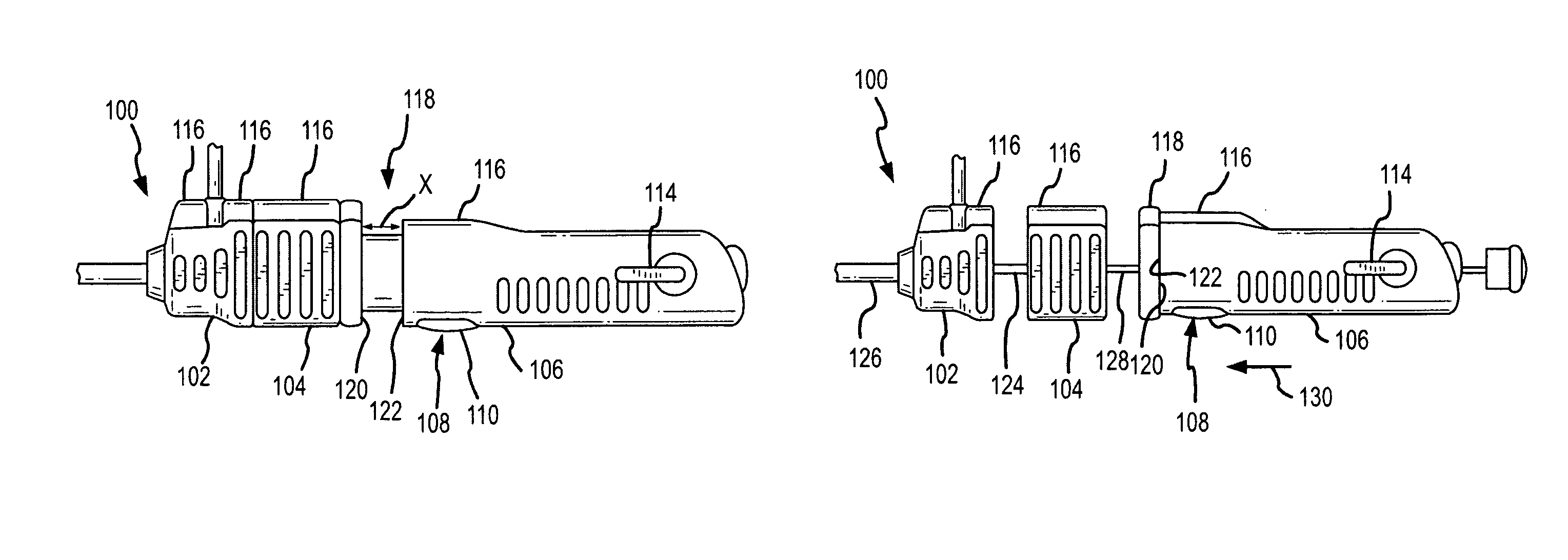
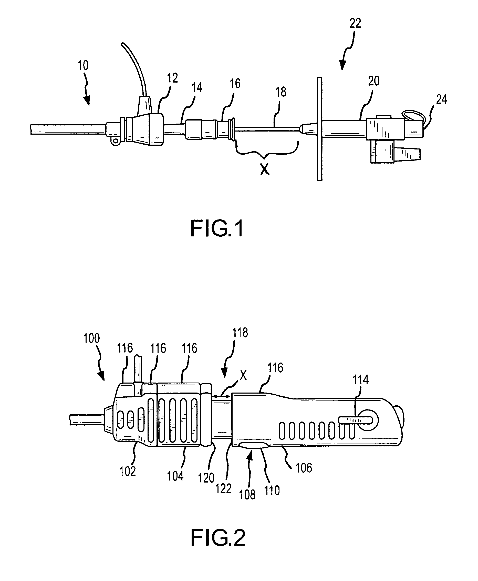
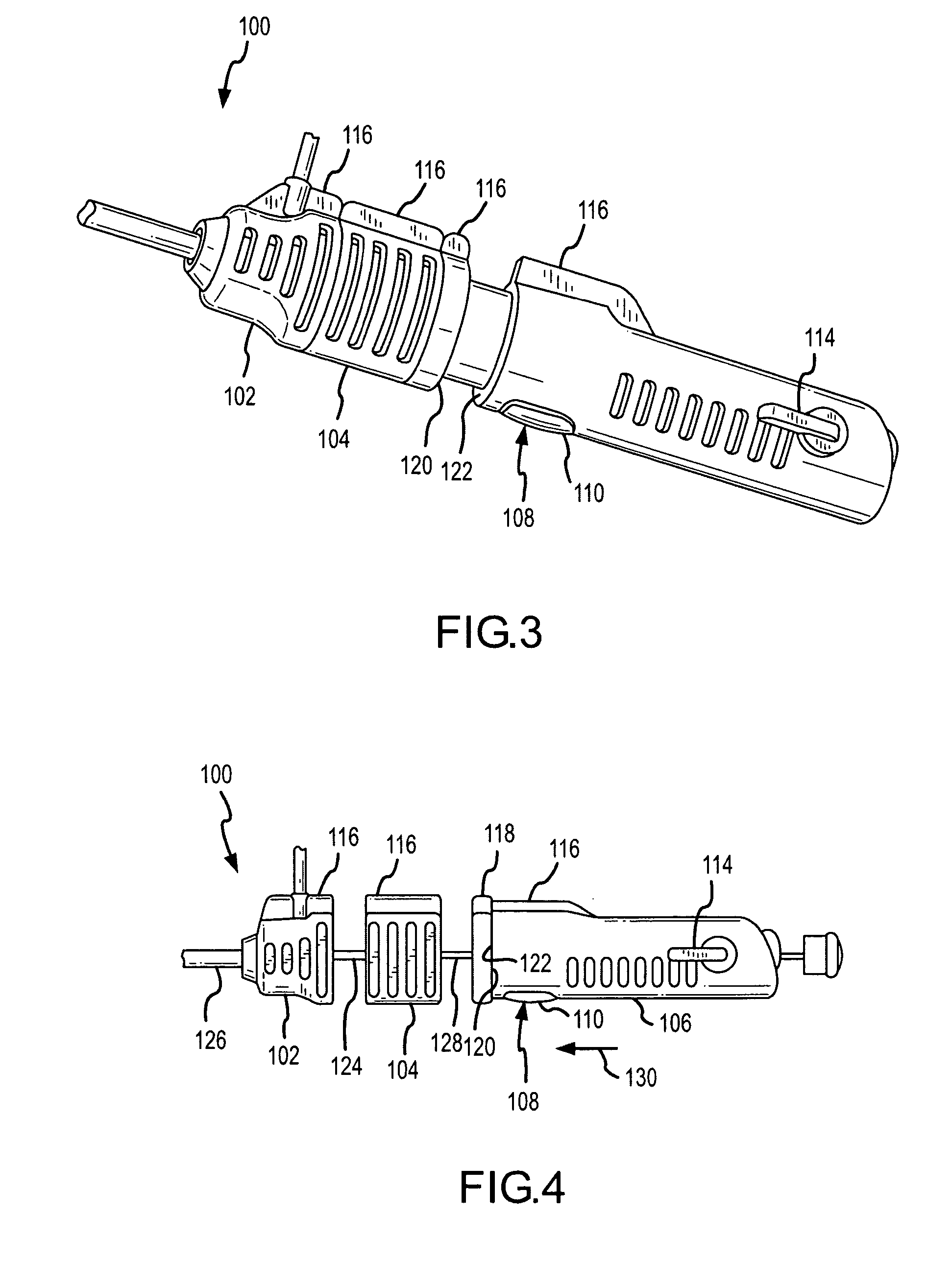
[0017]After removing the stylet, the needle is advanced through the sheath and the dilator until the distal end of the needle is just inside the distal end of the dilator. The present invention provides a stop mechanism to provide tactile feedback to the physician when the needle reaches this point. This mechanical stop also prevents unintentional advancement of the needle out of the dilator which may cause harm to the patient during use. For example, in FIG. 2, this feature includes an extension of the needle hub configured to include a spacer having a length (X) that corresponds to the distance the needle extends from the dilator at the distal end of the assembly when fully extended. The needle stop mechanism is held in place by a locking mechanism that can be activated by a button, or other activation device.Needle Advance Mechanism
[0019]Upon completion of the septal puncture, and after the needle is advanced through the tissue, the handheld mechanism preferably includes an additional mechanism to facilitate advancement of the sheath and dilator into the left atrium. One embodiment of this concept utilizes an extension on the distal end of the needle hub which can push the sheath and dilator hub forward. This allows the physician to advance the dilator and sheath over the needle with more stability and control.
[0020]In accordance with the present invention, these features and mechanisms are combined to provide an improved cooperative handle assembly for use in transseptal catheterization procedures utilizing a sheath assembly, a dilator assembly and a needle assembly comprising a sheath hub, a dilator hub removably connected to the sheath hub, a needle hub removably connected to the dilator hub, and a needle advancement mechanism adapted to cooperate with the needle assembly, whereby the needle advancement mechanism allows for selective advancement of the needle assembly from a position within a dilator to a position external to the dilator.
[0021]Additionally, the present invention provides for a method for manufacturing a handle assembly comprising the following steps: providing a sheath hub, a dilator hub, and a needle hub; removably connecting the dilator hub to the sheath hub; removably connecting the needle hub to the dilator hub; disposing a needle assembly at least partially within the needle hub; and connecting a needle advancement mechanism to the needle assembly, whereby the needle advancement mechanism allows for selective advancement of the needle assembly from a position within a dilator to a position external to the dilator.
[0023]The present invention provides a number of advantages, including, for example, provision of an intuitive, inter-locking proximal handle which organizes components and makes them easy to manipulate. The present invention improves current transseptal puncture procedures by: (1) safely and reliably locating the tip of the needle within the dilator; and (2) reducing procedural complexity by simplifying the proximal end of the current tool set, allowing the physician to focus on the other aspects of the procedure. The present invention includes the additional advantage of including a mechanical stop to prevent unintentional advancement of the needle. Further advantageous safety features include a release button for advancement of the needle.

Problems solved by technology

The most difficult chamber of the heart to access with a catheter is the left atrium.
Access to the left atrium through the pulmonary artery is not possible.
Approaches from the left ventricle are difficult, may cause arrhythmias and may present difficulty in obtaining stable catheter positioning.
Clearly, this method is an imprecise approximation of the position and lends itself to adjustment errors and difficulties.
This method, however adds significant expense and complications to the procedure.
A number of risks, in addition to the risks associated with normal heart catheterization, are inherent in transseptal catheterization.
For example, a major risk present stems from the use of known transseptal devices, which typically have a puncture device, or needle, that can be inadvertently exposed during the procedure.
Moreover, the known assemblies are cumbersome and difficult to operate.
Thus, a significant drawback with current transseptal tools lies in the fact that the tools are effectively three separate components that operate independently of one another.
This independence introduces significant difficulties to a user in that they must all be manipulated, or held in place, independently through manual efforts of the user.

Method used


Image

  • Transseptal catheterization assembly and methods
  • Transseptal catheterization assembly and methods
  • Transseptal catheterization assembly and methods

Examples


second embodiment

[0060]FIGS. 5A and B identify an improved handle assembly in accordance with the present invention. The handle assembly 200 has cooperating hub assemblies for the sheath 202, dilator and needle assemblies 206 used in transseptal procedures. The hub assemblies of each of these components are preferably preformed having corresponding removably attachable locking mechanisms (not shown). The locking mechanisms include for example, snap-fit assembly, or spring or lever biased latches for removable coupling. The assembly further has a two-way or three-way adjustable valve 208 disposed within needle hub assembly 206. At least one of the hub assemblies further includes an orientation member 210, e.g., a fin, that serves to visually identify the orientation of the particular assembly inside the body and to help maintain the proper orientation the members during a transseptal procedure.

[0061]Additionally, the dilator hub 204 and the needle hub 206 are separated by at least one removable space...

third embodiment

[0063]FIG. 6A-6C identify an improved handle assembly in accordance with the present invention. The handle assembly 300 has many similar features to those described in FIGS. 2-4. In addition, the handle assembly in 300 further includes two button-release assemblies 302, 304, one for removably coupling the sheath hub and the dilator hub and the other for coupling the needle hub to the needle stop mechanism 312. Alternatively, the needle hub 310 may comprise a ridge 314 (in this case an annular ridge) surrounding the distal portion of the needle hub, or any other structure that applies tactile resistance. This ridge 314 interfaces with the proximal portion of the needle stop mechanism 312 and serves to provide a temporary stop for the needle assembly 310. Thus, the assembly FIG. 6A is shown in the needle stop position. In use, the user inserts the needle assembly 310 to a desired predetermined position within the dilator 316 by pressing the assembly 310 forward until the ridge 314 mee...

fourth embodiment

[0065]FIG. 7A-7B identifies an improved handle assembly in accordance with the present invention. The handle assembly 400 according to this embodiment has a sheath hub 402 located at the distal end of the assembly 400, a dilator hub 404 proximate the sheath hub, and a needle hub 406 located at the proximal end of the assembly. The hub assemblies of each of these components are preferably preformed and may have corresponding removably attachable locking / mating mechanisms. The assembly further comprises a safety latch 408 as a needle lock mechanism of a predetermined length that is pivotally connected to the needle hub 406, such that when it is in a locked position (see FIG. 7A), the distal end 410 of the safety latch 408 abuts the proximal end 412 of the front portion 414 of the needle hub 406. In this position, the needle assembly 406 is prevented from being advanced forward, thereby preventing the distal end of the needle from being extended beyond the distal end of the dilator 416...


PUM


Abstract

Improved hand assemblies and methods combining a number of the separate known devices used in transseptal catheterization procedures, including sheaths, dilators, and needle assemblies (including a puncture device and a stylet, for example). The hand assemblies provide cooperating members that reduce the overall complexity and increase safety of transseptal catheterization procedures.

Description

CROSS REFERENCE TO RELATED APPLICATIONS[0001]This application claims the benefit of U.S. provisional application No. 60 / 800,854, filed 17 May 2006, which is hereby incorporated by reference as fully set forth herein.BACKGROUND OF THE INVENTION[0002]a. Field of the Invention[0003]The instant invention relates to assemblies and methods for puncturing, or piercing, tissue within the body, including, for example, transseptal access systems and methods for accessing the left atrium from the right atrium by crossing the fossa ovalis. In particular, the instant invention is directed toward medical devices used with catheter assemblies in cardiology procedures that require tissue punctures, or piercings, such as transseptal punctures. More specifically, the instant invention relates to improved hand assemblies and methods combining a number of the separate devices used in transseptal catheterization procedures, including sheaths, dilators, and needle assemblies (including a puncture device ...

Claims


Application Information

Patent Timeline
Patent Type & Authority Patents(United States)
IPC IPC(8): A61M5/178A61B17/00A61B17/34A61M25/00A61M25/06A61B18/00
CPCA61B17/00234A61B17/3478A61B2017/00247A61B2017/0046A61B2018/00392A61M25/0084A61M2025/0681A61B2090/034
Inventor STANGENES, TODDSCHMIDT, BRIANKHIEU, XUAN
Owner ST JUDE MEDICAL ATRIAL FIBRILLATION DIV
Learn More