Apparatus for laying fiber tapes

a technology of fiber tapes and apparatuses, applied in the direction of adhesives, chemistry apparatus and processes, domestic applications, etc., can solve the problem that the width of the pressure plate provided with the roller can remain limited to the width of the roller

Active Publication Date: 2016-05-03
GFM GMBH
View PDF15 Cites 0 Cited by
  • Summary
  • Abstract
  • Description
  • Claims
  • Application Information

AI Technical Summary

Benefits of technology

[0005]The invention is thus based on the object of providing a deflection guide for the fiber tapes in an apparatus for laying fiber tapes, which deflection guide, under advantageous frictional conditions, allows good pressing of the fiber tapes against the already laid fiber layers on the one hand and secure removal of the adhesive tape from the fiber layer on the other hand, without giving rise to the likelihood that the fiber layer is partly lifted from the fiber structure again during the removal of the adhesive tape.
[0007]Since through these measures it is not the rollers as such that are pressurized, but the pressure plates having the rollers for the deflection of the tape, there are no limitations concerning the bearing of the rollers so that rollers with a respectively small diameter can be used with the effect that the fiber tape can be applied with advantageous pressing pressure to the already laid fiber structure without impairing simple removal of the adhesive tape from the fiber layer. Despite the bearing of the rollers for the deflection of the tape via retainers that are provided to the side of the pressure plates, the width of the pressure plates provided with the rollers can remain limited to the width of the rollers because the retainers arranged laterally on the pressure plates displaceably engage in the pressing direction in recesses of the adjacent pressure plates with the sliding surfaces. The mutually independent pressurization of the pressure plates with and without rollers via a common membrane is thus ensured without having to provide a distance between the pressure plates. Although the pressure plates with the rollers between the pressure plates must be provided with a sliding surface for deflection of the tape, the frictional resistance between the deflection guide arranged in accordance with the invention and the fiber tapes is considerably reduced in comparison with known deflection guides pressure plates without rollers. Especially simple constructional conditions are obtained in this connection if the rollers are held on shafts held in retainers arranged laterally on the pressure plates.
[0008]If sliding shoes which are offset from the remaining plate body and are resilient in the pressing direction are formed by the recesses for accommodating the retainers, the additional advantage is obtained that said sliding shoes, in the case of a respective resilient pretensioning, are able to follow the respective surface shape of the already formed fiber structure irrespective of the individual pressurization of the pressure plates, thus providing especially advantageous pressing conditions for the fiber tape which is substantially independent of the local deformation properties of the membrane. A further graduation in the pressurization of the fiber tapes over their width can be achieved in such a way that the sliding shoes of the pressure plates are subdivided into sliding segments by slits parallel to the plane of the plates. The pressurization steps formed by the respectively pretensioned sliding segments allow a mutually independent pressurization of the fiber tape in the region of each sliding segment, thus providing especially favorable conditions for applying the fiber layers of the fiber tape to the already laid fiber layers.
[0009]An effect which is comparable to the resilient sliding shoes can be achieved for the rollers for the deflection guidance of the fiber tapes in such a way that the rollers arranged as grooved pulleys are held by radial contact on bearing receivers supported in the pressing direction in a resilient fashion against the retainers by means of continuous elastic endless belts which are guided about a bearing roller. As a result of the resiliently supported bearing receivers for the grooved pulleys, they can be pretensioned following a pressurization of the pressure plates via the resiliently supported bearing receivers, so that the grooved pulleys, within the scope of this pretensioning, are able to follow the already provided fiber structure independently from each other. The mutually laterally supported grooved pulleys are held in engagement with the bearing receiver by means of the endless elastic continuous belts, wherein the elastic expansion of said endless belts is necessary for permitting the displacements of the grooved pulleys in the pressing direction which is enabled by the pretensioned bearing receivers. The bearing receivers are held in a clamped fashion between the lateral retainers, which thus form an abutment for the spring elements of the bearing receivers.
[0010]As a result of the potential resilient pretensioning both of the sliding shoes of the one pressure plates and also the grooved pulleys of the other pressure plates, individual pressurization of the pressure plates can be omitted especially for thin fiber tapes, thus providing simple constructional conditions because the individual plates merely need to be combined in a non-displaceable manner in a frame, which is subjected to a respective pressure force for pretensioning the sliding shoes or the grooved pulleys.

Problems solved by technology

Despite the bearing of the rollers for the deflection of the tape via retainers that are provided to the side of the pressure plates, the width of the pressure plates provided with the rollers can remain limited to the width of the rollers because the retainers arranged laterally on the pressure plates displaceably engage in the pressing direction in recesses of the adjacent pressure plates with the sliding surfaces.

Method used


Image

  • Apparatus for laying fiber tapes
  • Apparatus for laying fiber tapes
  • Apparatus for laying fiber tapes

Examples


Embodiment Construction

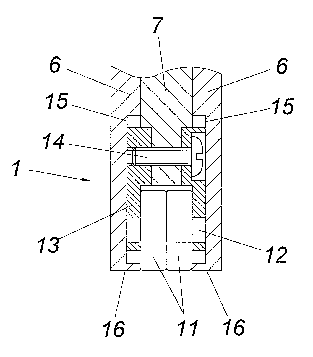
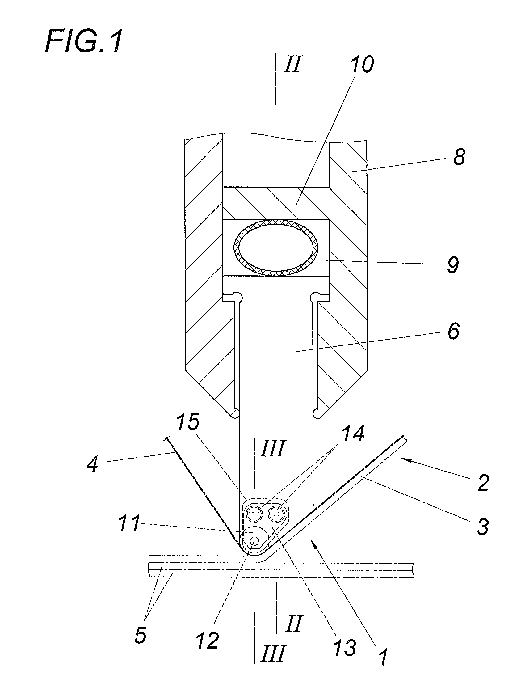
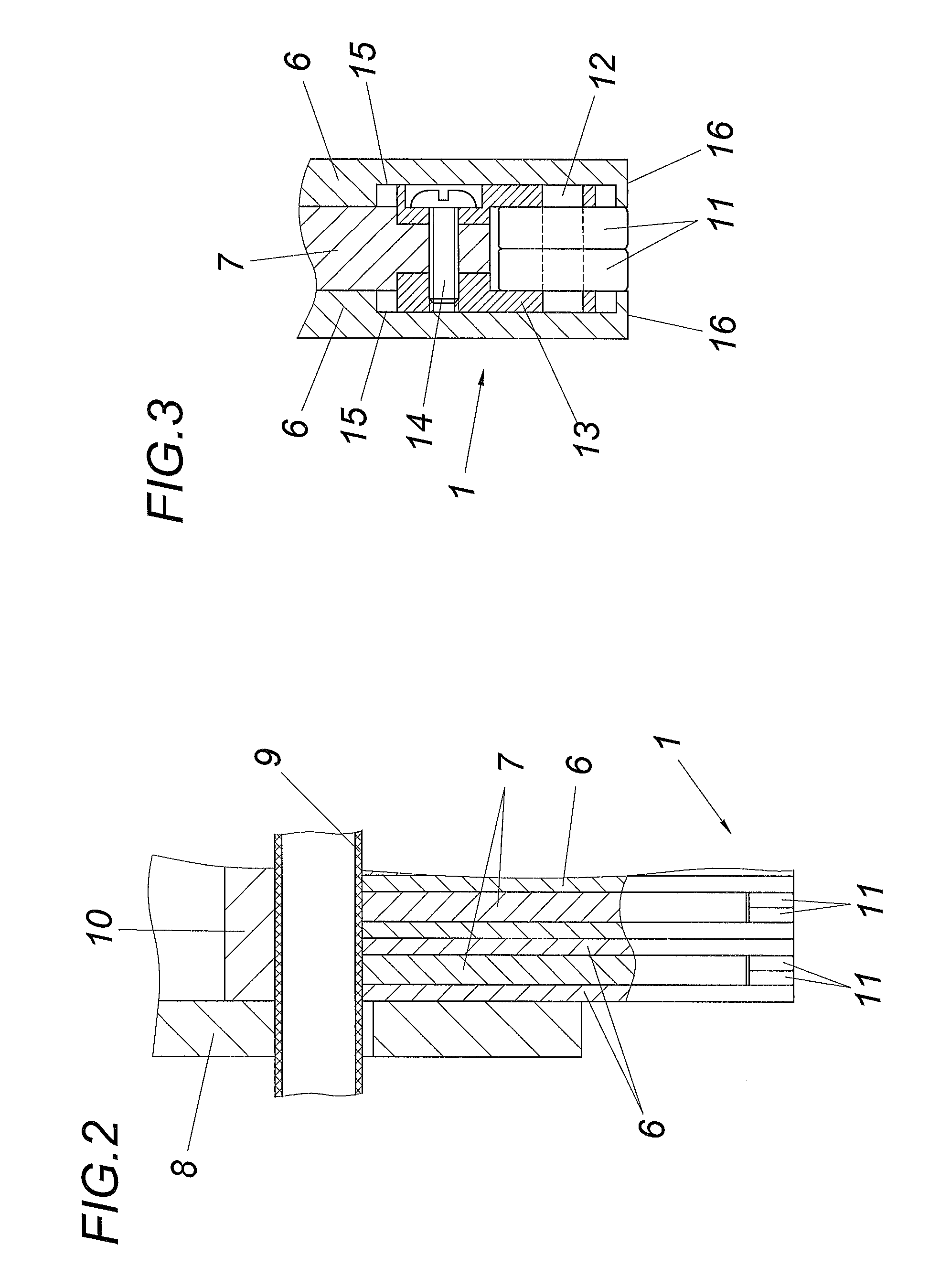
[0020]In accordance with the embodiment according to FIGS. 1 to 3, the apparatus comprises a laying head with a deflection guide 1 for the fiber tapes 2 having an adhesive tape 4 carrying a fiber layer 3. Said fiber tapes 2 are drawn off a supply roll and pressed by means of the deflection guide 1 against the already laid fiber layers 5 of a fiber structure to be formed, wherein the adhesive tape 4 is drawn off the fiber layer 3 of the fiber tape 2, which occurs at a comparatively small deflection radius. The deflection guide 1 is composed of a plurality of pressure plates 6 and 7 which are arranged next to one of other perpendicularly to the deflection axis and which are displaceably guided in a frame 8 in the pressing direction and are pressurized by means of a membrane 9 together with a pressure medium. In order to achieve simple constructional conditions, the membrane 9 is formed in the embodiment by a pressure hose which rests as an abutment on the side of a frame wall 10 which...


PUM

PropertyMeasurementUnit
deflection radiusaaaaaaaaaa
flexibilityaaaaaaaaaa
frictionaaaaaaaaaa

Abstract

An apparatus for laying fiber tapes includes a deflection guide for the fiber tapes made up of pressure plates arranged adjacent to one another transversely to the deflection axis and a frame for receiving the pressure plates which is displaceable in the laying direction. Pressure plates with rollers for deflecting the tape are provided between the pressure plates with a sliding surface for the deflection of the tape, and the retainers for the rollers, which retainers are arranged laterally on the pressure plates, displaceably engage in the pressing direction in recesses of the pressure plates with the sliding surfaces.

Description

CROSS REFERENCE TO RELATED APPLICATIONS[0001]Applicant claims priority under 35 U.S.C. §119 of Austrian Application No. A50830 / 2013 filed Dec. 16, 2013, the disclosure of which is incorporated by reference.FIELD OF THE INVENTION[0002]The invention relates to an apparatus for laying fiber tapes, comprising a deflection guide for the fiber tapes consisting of pressure plates arranged adjacent to one another transversely to the deflection axis and a frame for receiving the pressure plates which is displaceable in the laying direction.DESCRIPTION OF THE PRIOR ART[0003]Laying heads with a deflection guide for the fiber tapes are usually used for producing fiber structures, which laying heads are pressed against the already laid fiber layers by means of the adjacently arranged pressure plates which form the deflection guide. The fiber tapes, which comprise an adhesive tape carrying a fiber layer, are drawn off a supply roll to the extent of the forward feed movement of the laying head and...

Claims


Application Information

Patent Timeline
Patent Type & Authority Patents(United States)
IPC IPC(8): B29C70/38B32B37/12B32B37/00B32B37/10
CPCB32B37/0053B32B37/12B32B37/10B29C70/388B32B2305/28B32B2405/00
Inventor DIETACHMAYR, HARALD
Owner GFM GMBH
Why Eureka
Try Eureka