Saddle-type electric vehicle

a technology of electric vehicles and control units, which is applied in the direction of electric propulsion mounting, cycle equipment, electric propulsion devices, etc., can solve the problems of increasing the wheel base, difficult to secure the space to dispose of the control unit between the electric motor and the battery, and limited vertical space between the battery and the output shaft, so as to reduce the length of wiring, increase the rigidity of the vehicle body frame, and reduce the effect of electrical power loss

Active Publication Date: 2016-05-03
YAMAHA MOTOR CO LTD
View PDF49 Cites 22 Cited by
  • Summary
  • Abstract
  • Description
  • Claims
  • Application Information

AI Technical Summary

Benefits of technology

[0007]The layout in which the control unit is disposed rearward of the electric motor increases the length in the front-rear direction of the entire powertrain system device that includes the electric motor and the control unit. This potentially leads to an increase in the wheel base, and a decrease in distance (that is, the length of a rear arm that supports the rear wheel) from the powertrain system device to the rear wheel, and adversely affects the drivability of the vehicle.
[0014]In a saddle-type electric vehicle according to a preferred embodiment of the present invention, a front surface of the accommodating portion is preferably provided with a plurality of heat radiating fins. Since the accommodating portion is provided in a posture in which the length in the front-rear direction of the accommodating portion is less than the vertical height thereof, the front surface of the accommodating portion has a relatively large area. By providing the plurality of heat radiating fins at the front surface of the accommodating portion, it is possible to improve the cooling performance.

Problems solved by technology

A vertical space between the battery and the output shaft is limited.
For this reason, in the vehicle disclosed in JP 2010-18270 A, it is difficult to secure the space to dispose the control unit between the electric motor and the battery, and to prevents the portion of the vehicle that accommodates the control unit from overhanging rearward.
This potentially leads to an increase in the wheel base, and a decrease in distance (that is, the length of a rear arm that supports the rear wheel) from the powertrain system device to the rear wheel, and adversely affects the drivability of the vehicle.

Method used


Image

  • Saddle-type electric vehicle
  • Saddle-type electric vehicle
  • Saddle-type electric vehicle

Examples


Embodiment Construction

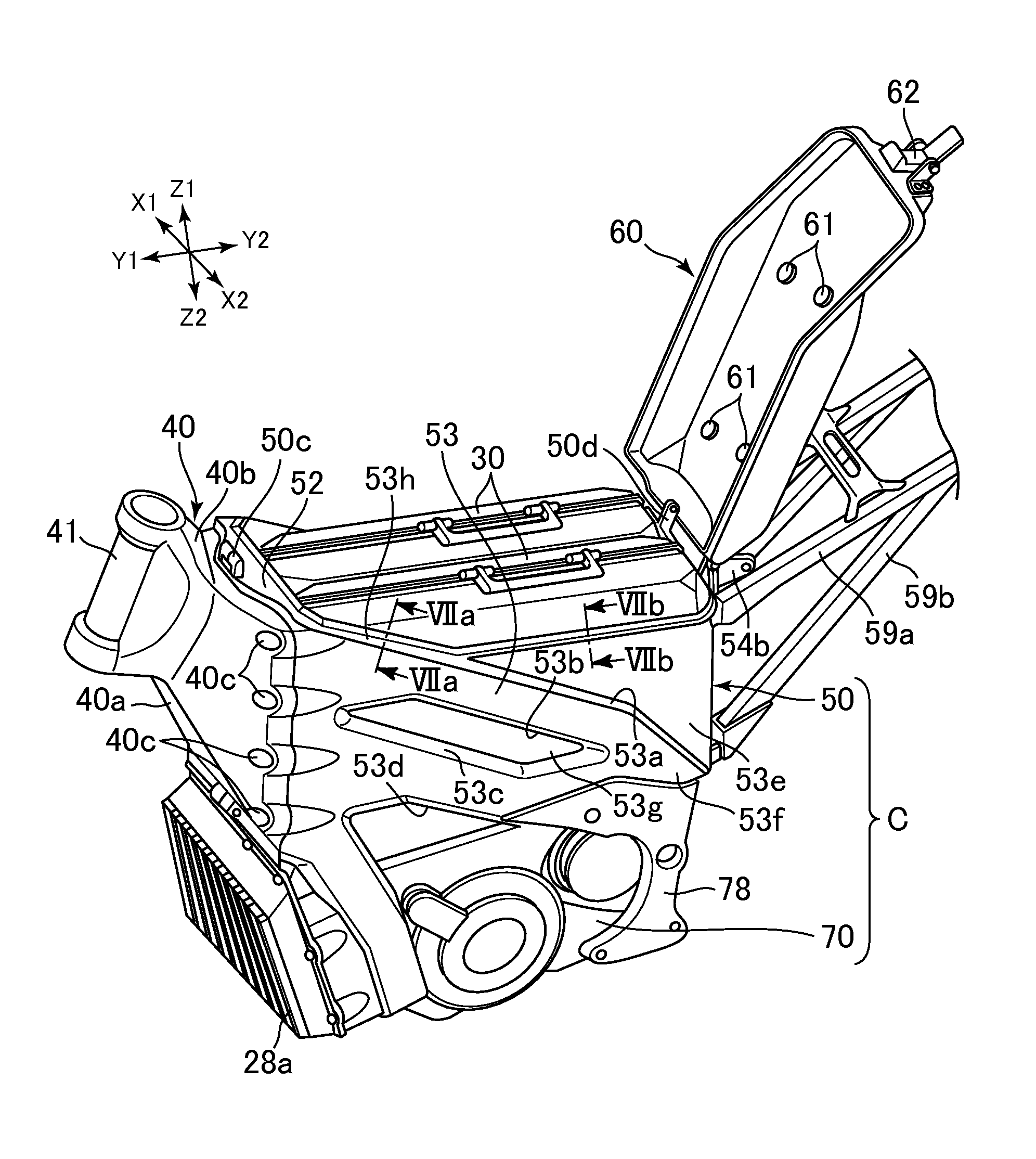
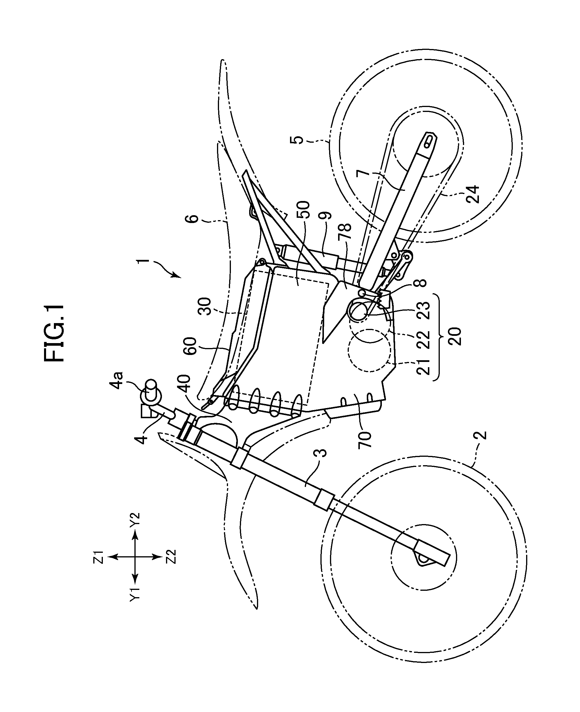
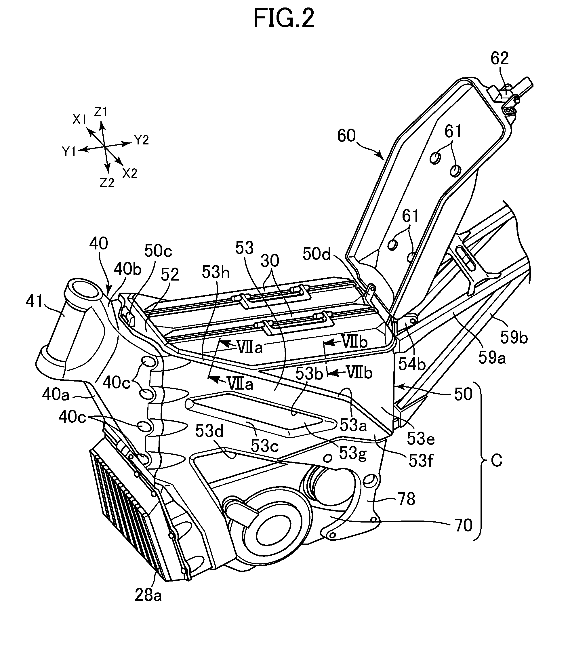
[0039]Hereinafter, a saddle-type electric vehicle and a battery equipped therein according to preferred embodiments of the present invention will be described. FIG. 1 is a side view of the saddle-type electric vehicle according to a preferred embodiment of the present invention. In this specification, an electric two-wheel vehicle 1 as an example of the saddle-type electric vehicle will be described. The saddle-type electric vehicle is not limited to an electric two-wheel vehicle, and may be a four-wheel all-terrain vehicle or recreational off-highway vehicle, for example. FIG. 2 is a perspective view illustrating a frame of the electric two-wheel vehicle 1. FIG. 3 is a plan view of a battery case 50 of the frame. FIG. 4 is a side view of a case C defined by the battery case 50 and a motor case 70 (to be described later). FIG. 5 is a side view illustrating an internal portion of the case C. In FIG. 5, a left case half body CL of the case C is partially removed.

[0040]In the following...


PUM


Abstract

A vehicle includes an electric motor disposed downward of a battery. The vehicle is provided with a motor control unit configured to receive electrical power from the battery and to supply the electrical power of the battery to the electric motor, and a case that accommodates the motor control unit. The case is positioned downward of the battery and forward of the electric motor, and is arranged in a posture in which the length in the front-rear direction of an accommodating portion in the case is less than the vertical height thereof in a side view of the vehicle body. Accordingly, a compact longitudinal layout of the electric motor and the motor control unit that controls the electric motor is achieved.

Description

CROSS-REFERENCE TO RELATED APPLICATION[0001]The present application claims priority from Japanese application JP 2013-230716 filed on Nov. 6, 2013, the entire contents of which are hereby incorporated by reference into this application.BACKGROUND OF THE INVENTION[0002]1. Field of the Invention[0003]The present invention relates to a layout of an electric motor, a battery, and a motor control unit in a saddle-type electric vehicle that is driven by an electric motor.[0004]2. Description of the Related Art[0005]The development of a saddle-type electric vehicle has made progress in which a rear wheel that is a drive wheel is driven by an electric motor. JP 2010-18270 A discloses an electric two-wheel vehicle as an example of the saddle-type electric vehicle. In the vehicle disclosed in JP 2010-18270 A, an electric motor is disposed below a battery that supplies electrical power to the electric motor. An output shaft is disposed rearward of the electric motor, and includes a sprocket ar...

Claims


Application Information

Patent Timeline
Patent Type & Authority Patents(United States)
IPC IPC(8): B60K1/04B62K11/04
CPCB60K1/04B62K11/04B62K2204/00B62K2208/00B62J43/16B62J43/20B62J43/28
Inventor MIYASHIRO, SHIDEHIKO
Owner YAMAHA MOTOR CO LTD
Why Eureka
Try Eureka