Electronic device and manufacturing method thereof

a manufacturing method and electronic technology, applied in the direction of optics, instruments, optical light guides, etc., can solve the problems of surface sinking on the welded portion, reduce the thickness of the welded portion, etc., and achieve the effect of reducing work time and cos

Active Publication Date: 2016-05-03
WISTRON CORP
View PDF2 Cites 0 Cited by
  • Summary
  • Abstract
  • Description
  • Claims
  • Application Information

AI Technical Summary

Benefits of technology

[0008]Utilizing the method for manufacturing the electronic device of the embodiment of the invention, the welded portion between the frame members is planarized by punch-shaping, and the material of the welded portion need not be removed. Therefore, a surface sinking problem at the welded portion is prevented in the following punch-bending process. Additionally, the appearance of the outer frame can be punch-shaped rapidly. Compared to the conventional polishing process, the method of the embodiment of the invention reduces work time and cost.

Problems solved by technology

However, the polishing process reduces the thickness of the welded portion, and the surface sinking occurs on the welded portion after the metal frame is punched and bent.

Method used


Image

  • Electronic device and manufacturing method thereof
  • Electronic device and manufacturing method thereof
  • Electronic device and manufacturing method thereof

Examples


Embodiment Construction

[0016]The following description is of the best-contemplated mode of carrying out the invention. This description is made for the purpose of illustrating the general principles of the invention and should not be taken in a limiting sense. The scope of the invention is best determined by reference to the appended claims.

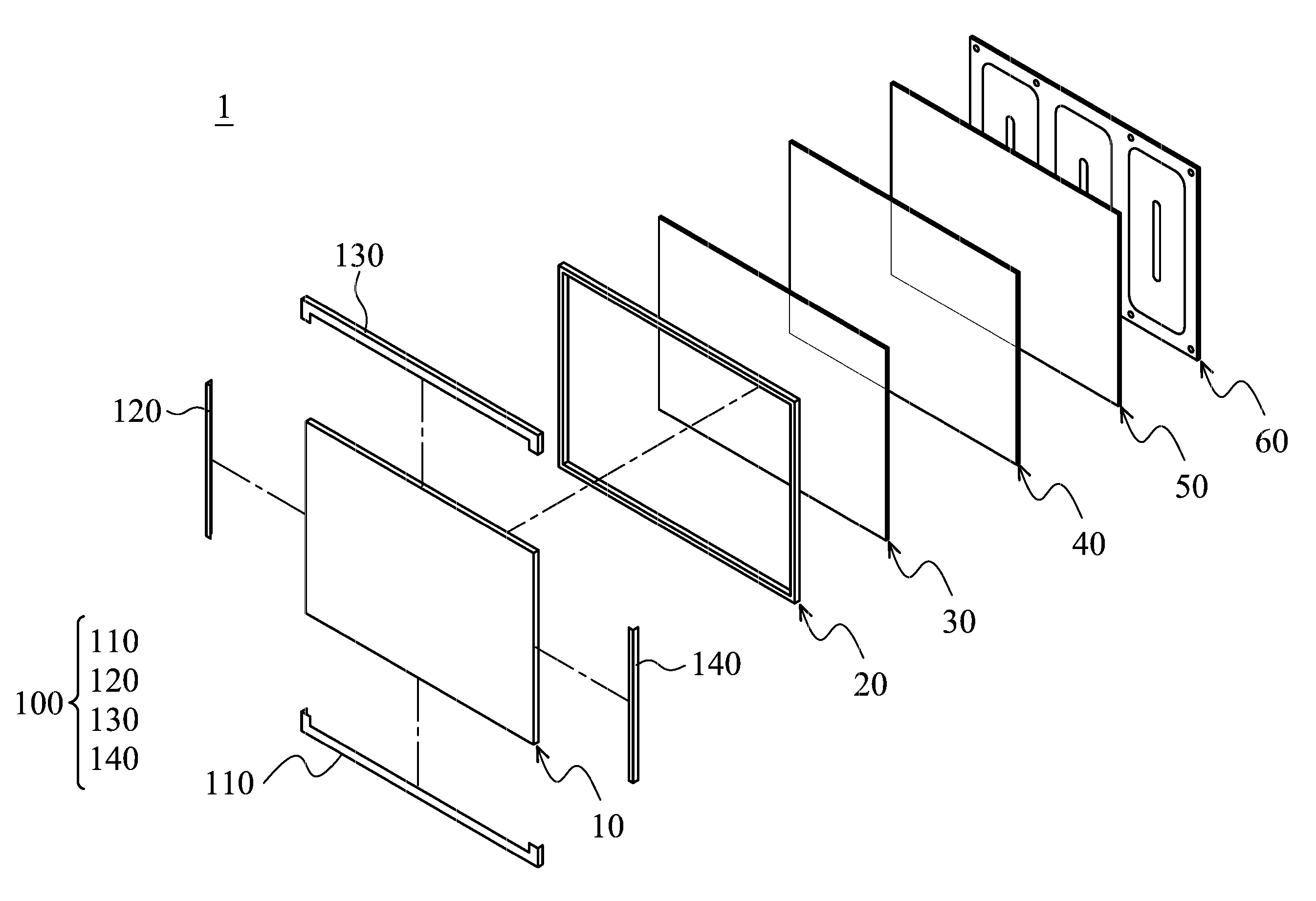
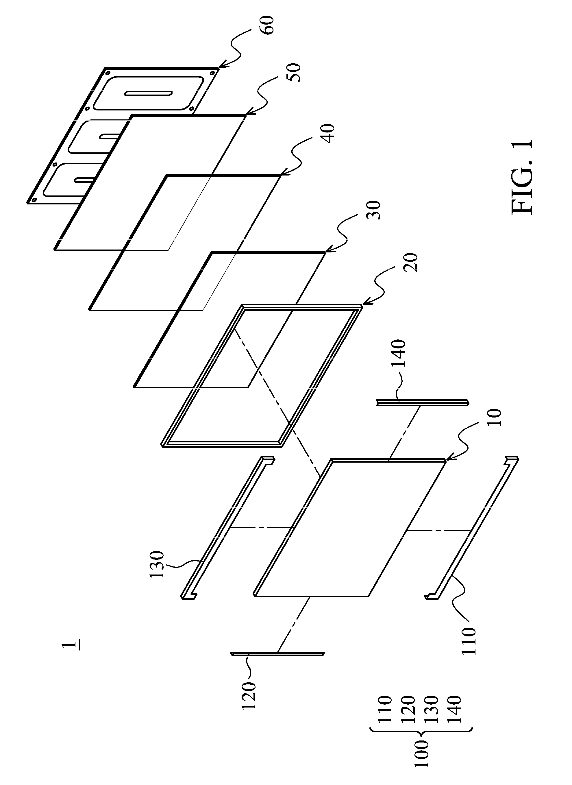
[0017]FIG. 1 shows an electronic device 1 of an embodiment of the invention, comprising a liquid-crystal display module 10, a plastic frame 20, a diffuser 30, a prism sheet 40, a light guide 50, a back panel 60 and an outer frame 100. The plastic frame 20, the diffuser 30, the prism sheet 40 and the light guide 50 are sandwiched between the liquid-crystal display module 10 and the back panel 60. The outer frame 100 comprises a first frame member 110, a second frame member 120, a third frame member 130 and a fourth frame member 140.

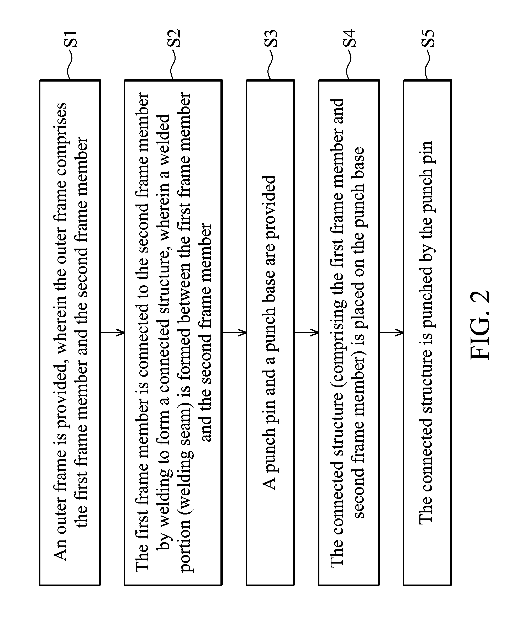
[0018]With reference to FIG. 2, a method for manufacturing the electronic device is described with the combination of the first frame member...


PUM

PropertyMeasurementUnit
widthaaaaaaaaaa
widthaaaaaaaaaa
widthaaaaaaaaaa

Abstract

A method for manufacturing an electronic device is provided, including the following steps. First, an outer frame is provided, wherein the outer frame comprises the first frame member and the second frame member. Next, the first frame member is connected to the second frame member by welding to form a connected structure, wherein a welded portion is formed between the first frame member and the second frame member. Then, a punch pin and a punch base are provided. Next, the connected structure is placed on the punch base. Finally, the connected structure is punched by the punch pin.

Description

CROSS REFERENCE TO RELATED APPLICATIONS[0001]This application claims priority of China Patent Application No. 201310513871.9, filed on Oct. 25, 2013, the entirety of which is incorporated by reference herein.BACKGROUND OF THE INVENTION[0002]1. Field of the Invention[0003]The present invention relates to a method for manufacturing an electronic device, and in particular to a method providing a smooth device appearance.[0004]2. Description of the Related Art[0005]The metal frame of a liquid-crystal television is made by combining separated pieces of sheet metal. Commonly, the metal frame is made by combining by four pieces of sheet metal (to form four sides of the metal frame), wherein the four pieces of sheet metal are connected to each other by welding. After the four pieces of sheet metal of the metal frame are welded together, the metal frame is punched to be bent. The welded portions (welding seams) between the pieces of sheet metal are not smooth. Conventionally, the welded port...

Claims


Application Information

Patent Timeline
Patent Type & Authority Patents(United States)
IPC IPC(8): G02F1/1333F21V8/00
CPCG02F1/133308G02B6/0051G02B6/0053G02F1/133504G02F1/133524Y10T29/49968G02F2001/133325G02F2001/13332G02F2001/133328Y10T29/49126G02F2001/133314G02F1/133325G02B6/0088G02F1/13332G02F1/133328G02F1/133314
Inventor DAI, SHU-HUA
Owner WISTRON CORP
Why Eureka
Try Eureka