Image processing apparatus and image processing method
a technology which is applied in the field of image processing apparatus and image processing method, can solve the problems that a slide glass and a specimen give rise to waviness in the slide, and achieve the effect of enhancing the throughput and response speed of the device and reducing computational costs
- Summary
- Abstract
- Description
- Claims
- Application Information
AI Technical Summary
Benefits of technology
Problems solved by technology
Method used
Image
Examples
embodiment 1
[0040][Embodiment 1]
[0041]Overall System Configuration
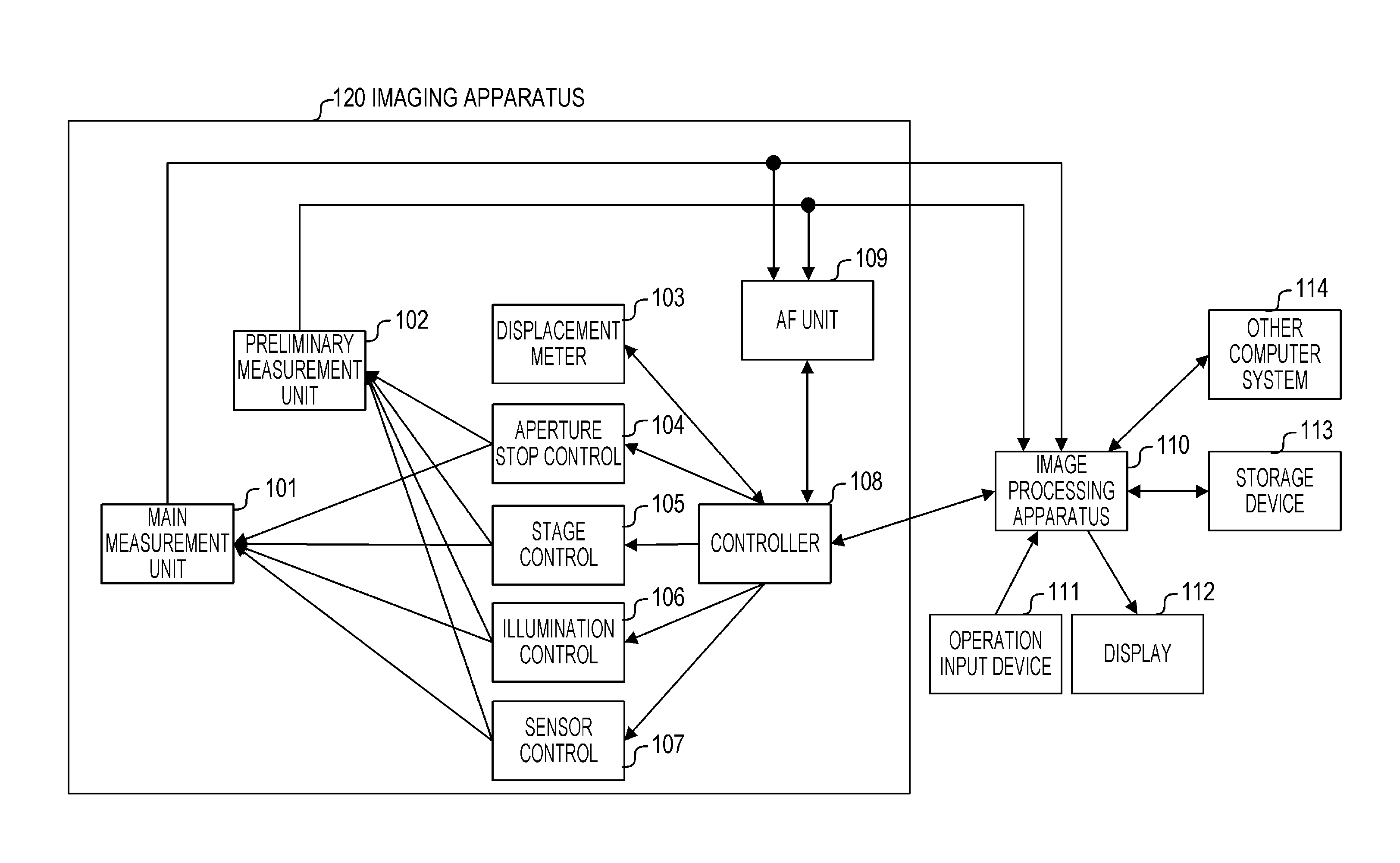
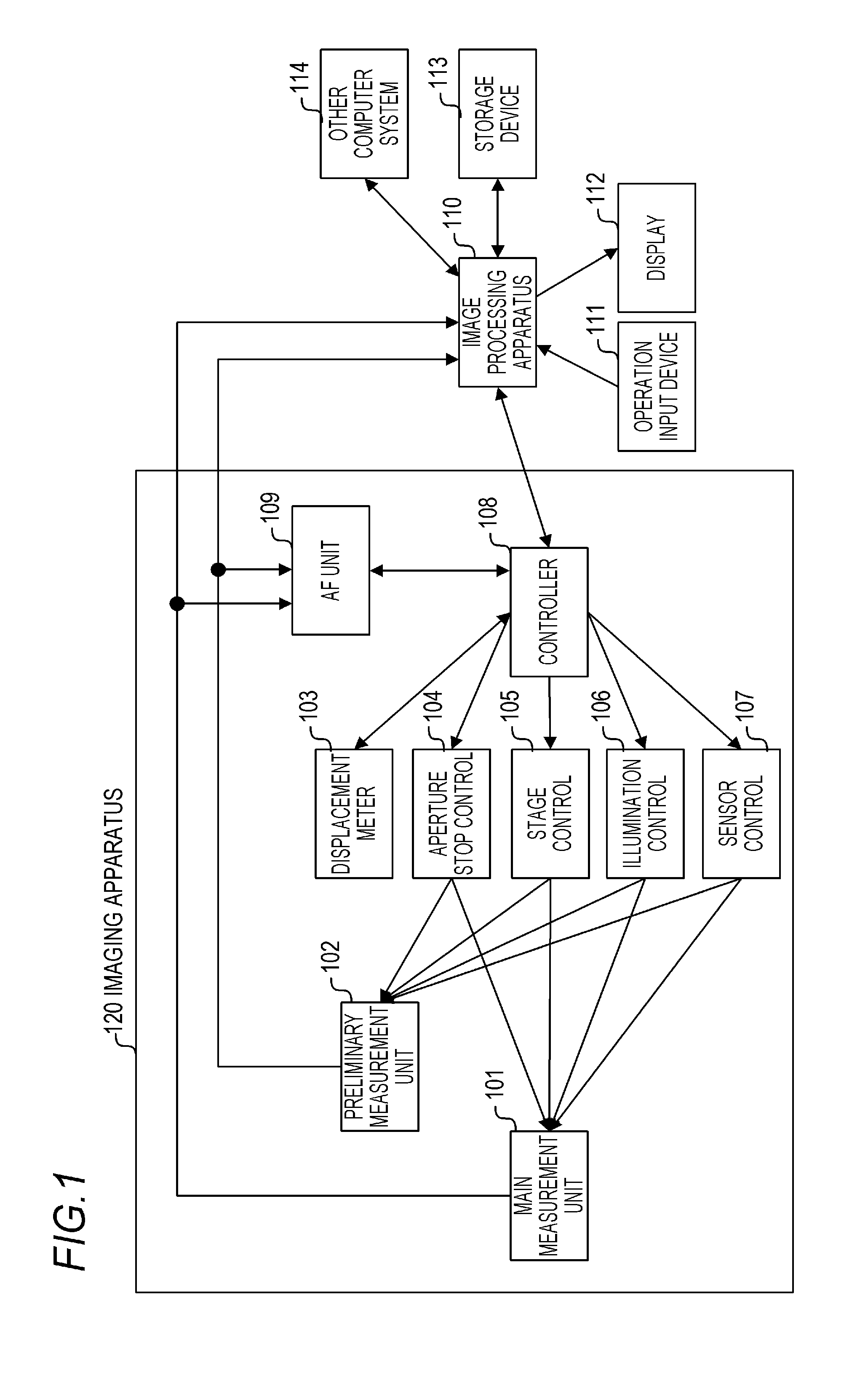
[0042]FIG. 1 illustrates the configuration of a virtual slide system that is one embodiment of the imaging system of the present invention.
[0043]The virtual slide system is made up of an imaging apparatus (also called a virtual slide scanner) 120 that acquires image data of a subject, an image processing apparatus (also called a host computer) 110 that performs data processing and control, and peripherals of the image processing apparatus 110.
[0044]The image processing apparatus 110 is connected to an operation input device 111, such as a keyboard, a mouse or the like, that receives inputs from a user, and a display 112 that displays processed images. A storage device 113 and another computer system 114 are connected to the image processing apparatus 110.
[0045]In a case where a plurality of subjects (slides) are batch-processed, the imaging apparatus 120 captures respective subjects, under the control of the image processing appa...
embodiment 2
[0187][Embodiment 2]
[0188]An explanation follows next on a depth-of-field extension method in a case where the Z position of the synthesis focal plane varies significantly between divisional imaging regions in the main measurement processing S403 in the present embodiment. The configuration of the present embodiment allows realizing the effect of increasing diagnosis efficiency for the user (pathologist) through generation of defocusing-free clear images at the focusing position, even in cases of slide waviness or ruggedness, or of substantial distribution position variability in cells and tissue within a specimen.
[0189]FIG. 16A illustrates the internal processing flow of the depth extension processing S404 in the present embodiment.
[0190]In depth extension characteristic information acquisition processing S2001, the image processing apparatus 110 acquires depth of field and imaging characteristic information after depth extension processing in accordance with a method identical to ...
embodiment 3
[0202][Embodiment 3]
[0203]An explanation follows next of processing, in the depth extension setting S401 of the present embodiment, that enables designating the depth extension original information that corresponds to a plurality of depth of fields, and generating a plurality of extended depth-of-field images. Generating a plurality of extended depth-of-field images having dissimilar depths of field makes it possible to generate, at one time, images that are obtained through the operation of an optical microscope, and to afford the effect of enhancing diagnosis efficiency for the user that utilizes the virtual slide.
[0204]The flow of processing will be explained with reference to FIG. 9A. Firstly, in the depth extension characteristic information acquisition processing S901, the image processing apparatus 110 acquires imaging characteristic information and a plurality of depths of field from depth extension original information that is set in depth extension setting S401. Next, in t...
PUM
 Abstract
Description
Claims
Application Information
 - R&D
- Intellectual Property
- Life Sciences
- Materials
- Tech Scout
- Unparalleled Data Quality
- Higher Quality Content
- 60% Fewer Hallucinations
Browse by: Latest US Patents, China's latest patents, Technical Efficacy Thesaurus, Application Domain, Technology Topic, Popular Technical Reports.
© 2025 PatSnap. All rights reserved.Legal|Privacy policy|Modern Slavery Act Transparency Statement|Sitemap|About US| Contact US: help@patsnap.com


