
Method, system and non-transitory computer-readable medium for forming a seismic image of a geological structure

a computer-readable medium and geological structure technology, applied in the field of seismic data, can solve the problems of affecting the accuracy of seismic images, so as to reduce the fd time dispersion error and the marginal computational cost

Active Publication Date: 2020-06-23
STATOIL GULF SERVICES +1
View PDF13 Cites 0 Cited by
  • Summary
  • Abstract
  • Description
  • Claims
  • Application Information

AI Technical Summary

Benefits of technology

The present invention provides a method, system, and computer-readable medium for creating a seismic image of a geological structure that can minimize errors caused by the FD time dispersion. This method can be implemented without significantly increasing computational cost.

Problems solved by technology

However, the wave propagation has dominated the computational time / cost for seismic imaging on complex geological structures, and the accuracy and efficiency of wave propagation are crucial to the success of real applications of these algorithms.
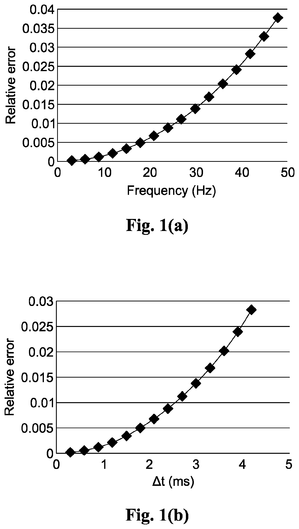
However, numerical dispersion due to discretization of time and space derivatives can introduce severe numerical errors in synthetic data and migrated images, especially when the sampling rate is large.
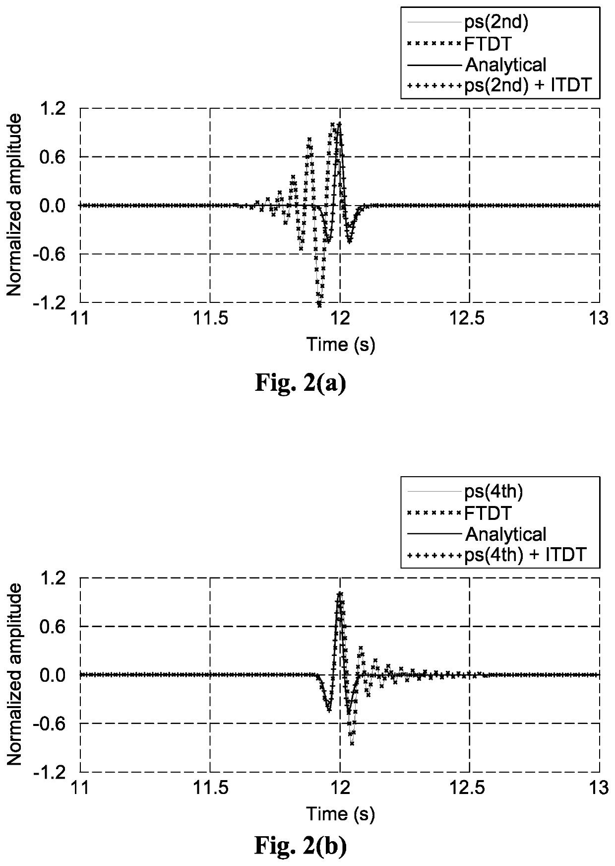
However, the time extrapolation calculated by one side extrapolation of time steps could not be easily implemented by spectral methods, introducing errors that are proportional to the time of propagation, and with phenomena that different frequency components of wavefields propagate with different velocities.
These time dispersion errors might distort the phase and introduce severe artifacts to the data and images, especially for long time propagation.
For seismic imaging, the time dispersion might cause mispositioning of reflectors, especially for deep reflectors with high frequency and imaged from long offset data.
Although the time dispersion errors may be improved by reducing the time steps used in the FD method, the computational cost dramatically increases.

Method used


Image

  • Method, system and non-transitory computer-readable medium for forming a seismic image of a geological structure
  • Method, system and non-transitory computer-readable medium for forming a seismic image of a geological structure
  • Method, system and non-transitory computer-readable medium for forming a seismic image of a geological structure

Examples


Embodiment Construction

[0027]The present invention will now be described in detail with reference to the accompanying drawings, wherein the same reference numerals will be used to identify the same or similar elements throughout the several views. It should be noted that the drawings should be viewed in the direction of orientation of the reference numerals.

[0028]The present invention is directed to reduction and / or elimination of the time dispersion errors such that more accurate seismic image of a geological structure can be formed without sacrificing computational efficiency or increasing computational cost.

[0029]In order to effectively reduce or eliminate the time dispersion errors, an investigation of the time dispersion problem is necessary. The investigation starts with a general wave equation. With absence of source term, the propagation can be described by Equation (1) as follows:

[0030]∂2⁢u∂t2-Lu=0,(1)

[0031]where

[0032]u=u({right arrow over (x)}, t) is the wavefield, which may represent pressure f...


PUM


Abstract

A method, system and non-transitory computer-readable medium for forming a seismic image of a geological structure are provided. After obtaining seismic wave data including a plurality of seismic wave traces at a first region of the geological structure, a predicted time dispersion error of an actual time dispersion error that results from a use of a finite difference approximation in calculating predicted seismic wave data at a second region of the geological structure as if a seismic wave propagates from the first region to the second region of the geological structure, is calculated. A corrected predicted seismic wave data at the second region of the geological structure is calculated by applying the finite difference approximation to the seismic wave data at the first region of the geological structure compensated with the predicted time dispersion error. A seismic image of the second region of the geological structure is generated using the corrected predicted seismic wave data, such that the actual time dispersion error is negated by the predicted time dispersion error.

Description

CROSS-REFERENCE TO RELATED APPLICATIONS[0001]NoneBACKGROUND OF THE INVENTION1. Field of the Invention[0002]The present invention relates to seismic data, and more particularly to a method, system and non-transitory computer-readable medium for forming a seismic image of a geological structure.2. Background of the Invention[0003]The research of seismic imaging on complex geological structures currently focuses on the development of algorithms that are based on two-way wave equations, such as reverse-time migration (RTM) and full-waveform inversion (FWI). However, the wave propagation has dominated the computational time / cost for seismic imaging on complex geological structures, and the accuracy and efficiency of wave propagation are crucial to the success of real applications of these algorithms. One commonly used method to calculate wave field is the finite difference (FD) method.[0004]To improve the efficiency of wave propagation calculation, conventional ways tend to use large sam...

Claims


Application Information

Patent Timeline
Patent Type & Authority Patents(United States)
IPC IPC(8): G01V1/28
CPCG01V1/28G01V2210/43G01V2210/673G01V2210/57G01V2210/582Y02A90/30
Inventor WANG, MEIXIAXU, SHENG
Owner STATOIL GULF SERVICES
Learn More