Fiber optic scanning interferometer using a polarization splitting coupler

Inactive Publication Date: 2005-05-12
FAILES MICHAEL
View PDF7 Cites 7 Cited by
  • Summary
  • Abstract
  • Description
  • Claims
  • Application Information

AI Technical Summary

Benefits of technology

[0011] A Michelson interferometer that uses a polarizing beam splitter coupler, where the signal is in the p mode and the reference signal is in the s mode, has the advantage that the zero optical path difference condition is not coincident with the zero physical path difference of the fiber arms.

Problems solved by technology

When interferometers are made with polarization preserving fiber, the effect of cross coupling from components and splices in the fiber path can produce unwanted signals due to the multiple optical paths that c

Method used


Image

  • Fiber optic scanning interferometer using a polarization splitting coupler
  • Fiber optic scanning interferometer using a polarization splitting coupler
  • Fiber optic scanning interferometer using a polarization splitting coupler

Examples


Example

[0023] The following illustrates the essential attributes of interferometry for understanding of the invention.

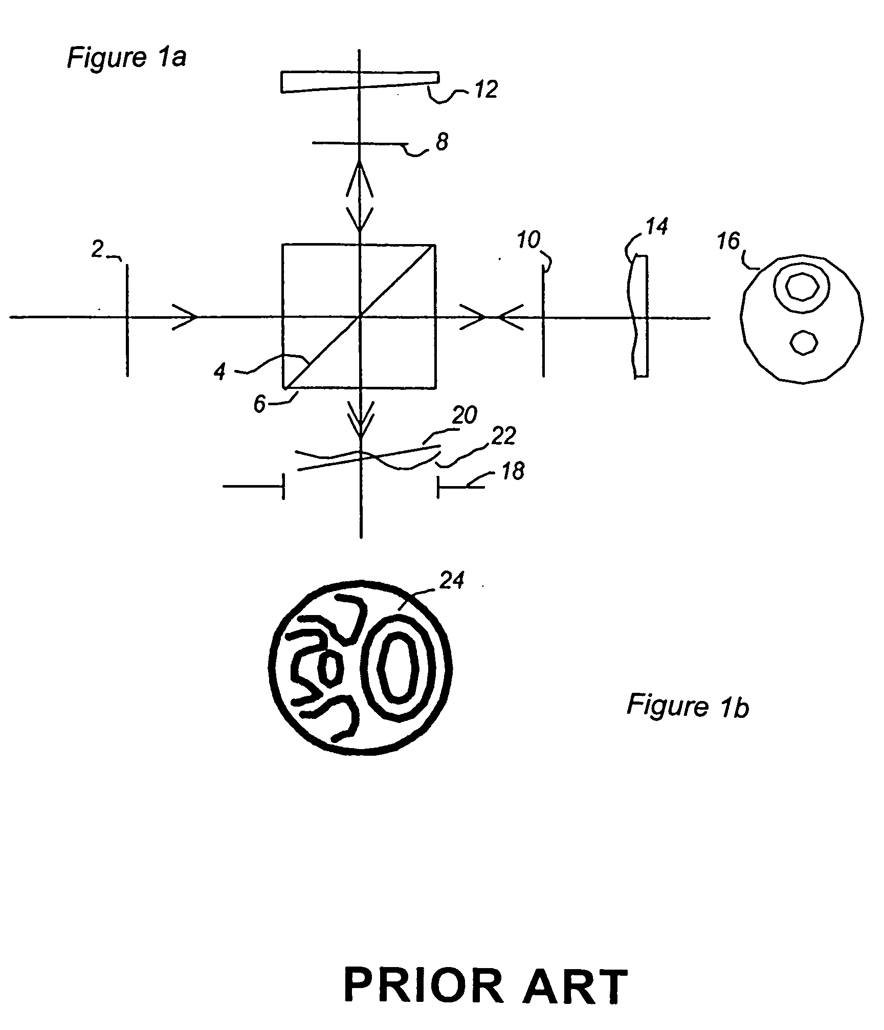
[0024] A Michelson interferometer is shown in FIG. 1. This arrangement demonstrates the phenomenon of optical interference between two wave fronts.

[0025] A source plane wavefront 2 is split by the diagonal face 4 of the beam splitter cube 6 into the plane wavefront 8 by reflection and plane wavefront 10 by transmission. Mirror 12, shown with a small tilt reflects the plane wavefront 8 which is transmitted by the beam splitter cube 6 to the output aperture 18 where it appears as a tilted wavefront 20. Mirror 14, shown with surface irregularity 16, reflects the plane wavefront 10 which is in turn reflected by the beam splitter cube 6 to the output aperture 18 where it appears as an irregular wavefront 22. The superposition of the wavefronts 20 and 22 gives the interface pattern of light and dark bands 24 (see FIG. 1b) called fringes.

[0026] The observed intensity of the fri...


PUM


Abstract

A fiber optic scanning interferometer in a Michelson arrangement using a polarization splitting coupler is disclosed. The splitting of s and p polarization modes into the fast and slow axes of a birefringent fiber allows the temporal separation of interference phenomena from multiple reflections such that signal recovery is simplified.

Description

BACKGROUND OF THE INVENTION [0001] 1. Field of the Invention [0002] In the application to optical coherence tomography, there is a need to detect reflecting and scattering targets within a sensing volume to determine the spatial distribution of the targets. The use of low coherence laser sources allows detection of reflecting and scattering targets by scanning optical paths through the zero path difference condition under which fringes can be observed. In the application to polarization mode dispersion (PMD), the source has passed through a long singlemode fiber and has accumulated phase and amplitude changes due to birefringence effects in that fiber which manifest as polarized modes which can be analyzed by observation of the fringes generated in a scan. [0003] 2. Discussion of the Prior Art [0004] There are many descriptions of fiber optic interferometers with optical path length modulation that give fringes. These devices are made in single mode (SM) standard fibers that exhibit...

Claims


Application Information

Patent Timeline
IPC IPC(8): G01B9/02G01J9/02G01N21/47
CPCG01J2009/0261G01B2290/70G01B9/02091G01N21/4795
Inventor FAILES, MICHAEL
Owner FAILES MICHAEL
Why Eureka
Try Eureka