Connection structure of column and beam, and reinforcing member

a technology of connecting structure and beam, which is applied in the direction of buildings, buildings, constructions, etc., can solve the problems of not being able to connect at least one of the upper and lower flanges of the beam to the through-diaphragm to which other beams are connected, and the height of the beams that are connected to the column is not equal

Active Publication Date: 2016-05-10
SENQCIA CO LTD
View PDF17 Cites 43 Cited by
  • Summary
  • Abstract
  • Description
  • Claims
  • Application Information

AI Technical Summary

Benefits of technology

[0021]The present invention can provide a connection structure and the like of a column and beams, wherein the beams having different heights are connected to the column without connecting diaphragms and the like to the inside of the column, which is also applicable even if a gap between the beam and the diaphragm is small.

Problems solved by technology

However, there are cases in which the sizes (heights) of the beams that are connected to the column are not equal in all directions.
In such cases, it is impossible to connect at least one of the upper and lower flanges of the beam to the through-diaphragm to which other beams are connected.

Method used


Image

  • Connection structure of column and beam, and reinforcing member
  • Connection structure of column and beam, and reinforcing member
  • Connection structure of column and beam, and reinforcing member

Examples


Embodiment Construction

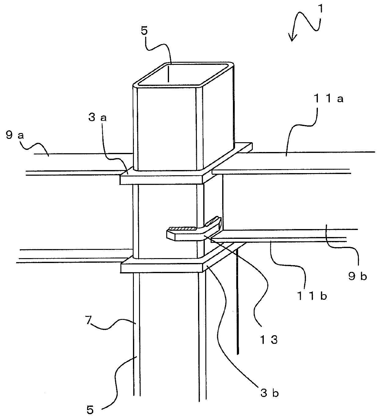
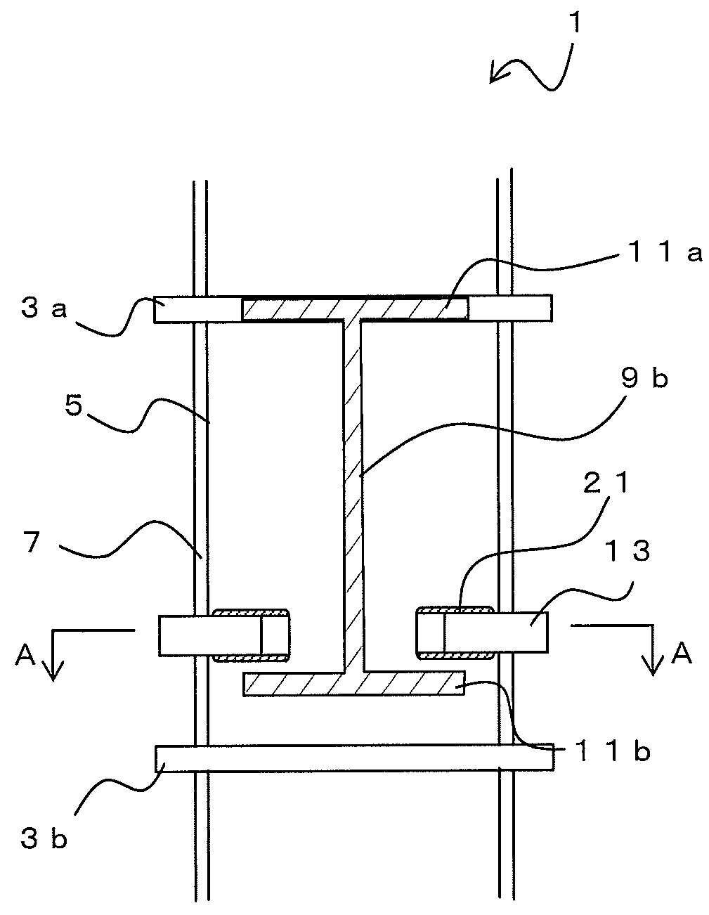
[0031]Hereinafter, a connection structure 1 of a column and beams according to an embodiment of the present invention will be described. FIG. 1 is a perspective view showing a connection structure 1 of a column and beams and FIG. 2 is a diagram viewed from the beam 9b side. The connection structure 1 of a column and beams is a structure having a column 5 to which a plurality of beams 9a and 9b are connected.

[0032]The column 5 is a hollow, square-shaped steel piped column of which the cross sectional outline is approximately rectangular. The beams 9a and 9b are H-shaped steel. The heights of the beams 9a and 9b are different. Although the example shown in FIG. 1 illustrates that the beam 9a is formed on the column 5 in a first direction and the beam 9b is formed in a direction opposing the first direction, the present invention is not limited to this case and the beam 9a or the beam 9b may be provided in a plurality of directions.

[0033]A pair of diaphragms 3a and 3b is connected to t...


PUM


Abstract

The reinforcing member 13 is an approximately L-shaped member. The reinforcing member 13 comprises a first connecting part 15a, which is connected to the connecting surface of the beam 9b of the column 5, and a second connecting part 15b, which is connected to a surface perpendicular to the surface to which the beam 9b is connected. That is, the connecting part 15a and the connecting part 15b are perpendicular to each other. A concave surface part 17 is provided on the inner surface side of the intersection of the connecting parts 15a and 15b. The reinforcing member 13 is, for example, made of steel having excellent weldability. On the connecting parts 15a and 15b, groove parts 19 are formed on the parts corresponding to the welding parts of the column 5.

Description

FIELD OF THE INVENTION[0001]The present invention relates to a connection structure of a column and beams and the like for connecting beams having different heights to a steel pipe column.BACKGROUND OF THE INVENTION[0002]Conventionally, in a construction using a steel pipe column, there is a case in which a beam of H shaped steel is connected. To connect the column and the beam, a through-diaphragm corresponding to the height of a flange part of the beam is provided to transfer stress from the beam to the column efficiently at a connecting part thereof. The through-diaphragm is a plate-like member that is connected by welding and the like between a column and a column. Generally, the flange part of the beam is butted against the side surface of the through-diaphragm to be welded.[0003]However, there are cases in which the sizes (heights) of the beams that are connected to the column are not equal in all directions. For example, there is a case in which a beam having a shorter height...

Claims


Application Information

Patent Timeline
Patent Type & Authority Patents(United States)
IPC IPC(8): E04H12/18E04B1/24
CPCE04B1/2403E04B2001/2406E04B2001/2454
Inventor TANAKA, HIDENORITOMITA, TAKU
Owner SENQCIA CO LTD
Why Eureka
Try Eureka