Speed sensor insert with bearing spacer indexing for a turbocharger

a technology of bearing spacer and turbocharger, which is applied in the direction of liquid fuel engines, instruments, machines/engines, etc., can solve the problems of damage accumulation, wheel overstress, and the inability to run in an overspeed condition of the turbocharger, and achieve the effect of easy removal

a technology of bearing spacer and turbocharger, which is applied in the direction of liquid fuel engines, instruments, machines/engines, etc., can solve the problems of damage accumulation, wheel overstress, and the inability to run in an overspeed condition of the turbocharger, and achieve the effect of easy removal

US9353760B2Active Publication Date: 2016-05-31BORGWARNER INC

Image

  • Speed sensor insert with bearing spacer indexing for a turbocharger
  • Speed sensor insert with bearing spacer indexing for a turbocharger
  • Speed sensor insert with bearing spacer indexing for a turbocharger

Examples


first embodiment

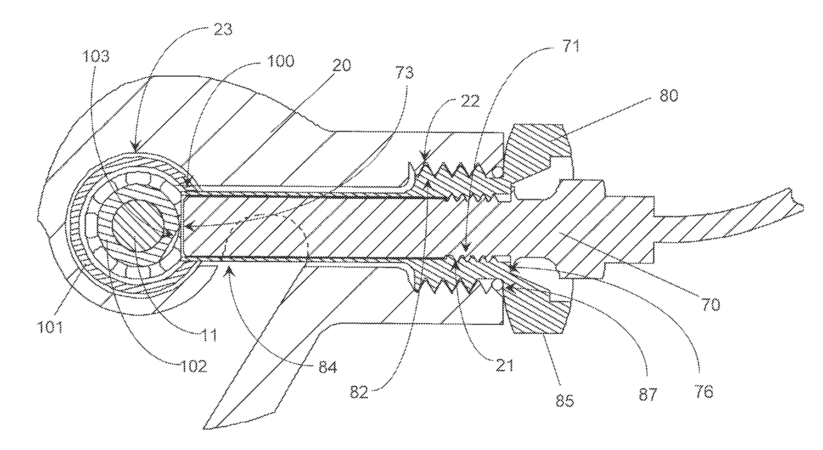
[0022]In the invention, as depicted in FIG. 4, an insert (80) is screwed into the bearing housing (20) to provide a mount for the speed sensor (70). The insert (80) has a feature (85), such as a hex or flats, so that it can be rotated to be screwed into the bearing housing (20). The insert has an externally facing thread (82) which can be threaded into an internally facing complementary thread (22) in the bearing housing (20). In the preferred mode of the invention, the insert (80) is sealed to the bearing housing (20) by an “0” ring or other suitable means such as tapered threads (86), and the depth of the nose of the insert in the bearing housing (i.e. the distance from the shaft (11) axis) is controlled by the distance from the inward facing surface (87) of the nut or locating feature to the inner end of the insert (80). The inward facing surface (87) of the nut or locating feature is axially constrained by an abutment on the bearing housing (20). The sensor (70) has an externall...

second embodiment

[0025]In the invention, as depicted in FIG. 6, for sensing the speed of the rotating assembly in turbochargers equipped with rolling element bearings (REB), the outside diameter of the inner race is equipped with a flat for the purpose of creating a cyclic signal for sensing the rotational speed of the inner race and thus the rotating assembly. In the case in which the inner race is axially split onto two pieces, the flat can be on either inner race piece as long as the sensor axis is axially aligned with the axis of the center of the flat so that the sensor can read a cyclic signal.

[0026]In the second embodiment of the invention, the shaft (11) for the rotating assembly is supported and located in an inner race (102) of an REB assembly. The REB assembly (or cartridge) is located within a bore (23) in the bearing housing (20). Typically, the outside diameter of the outer race (101), or in some cases the outside diameter of a cartridge, which contains the outer race (101), is support...


PUM


Abstract

A turbocharger bearing housing, including a bearing bore having two journal bearings located in the bearing bore and a tubular bearing spacer having first and second axial ends for spacing apart said journal bearings. The tubular bearing spacer having at least one radial opening and a mounting bore for receipt of a turbocharger shaft. The mounting bore further being capable of receiving a generally tubular insert mounted therein and extending into the at least one radial opening of the bearing spacer. The tubular insert further including an indexing surface to assist in setting the depth of insertion for a rotational speed sensor mounted therein via threaded fitting or friction fit and creating a set air gap between an end of the speed sensor and the rotating shaft.

Description

FIELD OF THE INVENTION[0001]This invention provides an improved means for securing a turbocharger speed sensor which also secures a journal bearing spacer against rotation.BACKGROUND OF THE INVENTION[0002]Turbochargers are a type of forced induction system. They deliver air, at greater density than would be possible in the normally aspirated configuration, to the engine intake, allowing more fuel to be combusted, thus boosting the engine's horsepower without significantly increasing engine weight. This can enable the use of a smaller turbocharged engine, replacing a normally aspirated engine of a larger physical size, thus reducing the mass and aerodynamic frontal area of the vehicle.[0003]The wheels in turbochargers are designed to operate at nearly maximum stress at the peak of the operating regime. This produces the best compromise between stress and mass, with respect to the design of the wheels, to provide the lowest inertia at the desired efficiency and pressure ratio for the ...

Claims


Application Information

Patent Timeline
31 May 2016
Publication
US9353760B2
IPC
F16C19/38; F16C19/52; F16C41/00; G01P3/44; F04D17/08; F04D29/056; F01D17/06; F04D29/40
CPC
F04D29/056; F01D17/06; F04D17/08; F04D29/403; F05D2220/40; G01P3/446; F02B37/22; F02B2037/122
Inventors
CHEKANSKY, JASON W.