Supercharge Your Innovation With Domain-Expert AI Agents!

Crossfire tube assembly with tube bias between adjacent combustors

a technology of crossfire tube and combustible, which is applied in the direction of continuous combustion chamber, combustion process, lighting and heating apparatus, etc., can solve the problems of retention clip or other clamp used damag

Active Publication Date: 2016-05-31
GENERAL ELECTRIC CO
View PDF31 Cites 4 Cited by
  • Summary
  • Abstract
  • Description
  • Claims
  • Application Information

AI Technical Summary

Benefits of technology

The present invention relates to a crossfire tube assembly between adjacent combustors in a gas turbine. One aspect of the invention is a telescoping sleeve that has a first end adapted to provide fluid communication from a first combustor and a second end adapted to provide fluid communication from a second combustor, with means for separating the first end from the second end. Another aspect is a crossfire tube assembly between adjacent combustors that includes a first sleeve and a second sleeve that extend at least partially inside the first sleeve, with a bias engaged between the first and second sleeves. These technical effects improve the stability and efficiency of gas turbines, resulting in better performance and reliability.

Problems solved by technology

For example, installation and removal of the crossfire tubes may result in damage to retention clips or other clamps used to hold the crossfire tubes in place.
In addition, the crossfire tubes may create flow instabilities of the compressed working fluid flowing around the crossfire tubes in the annular plenum between the flow sleeve and the liner.

Method used


Image

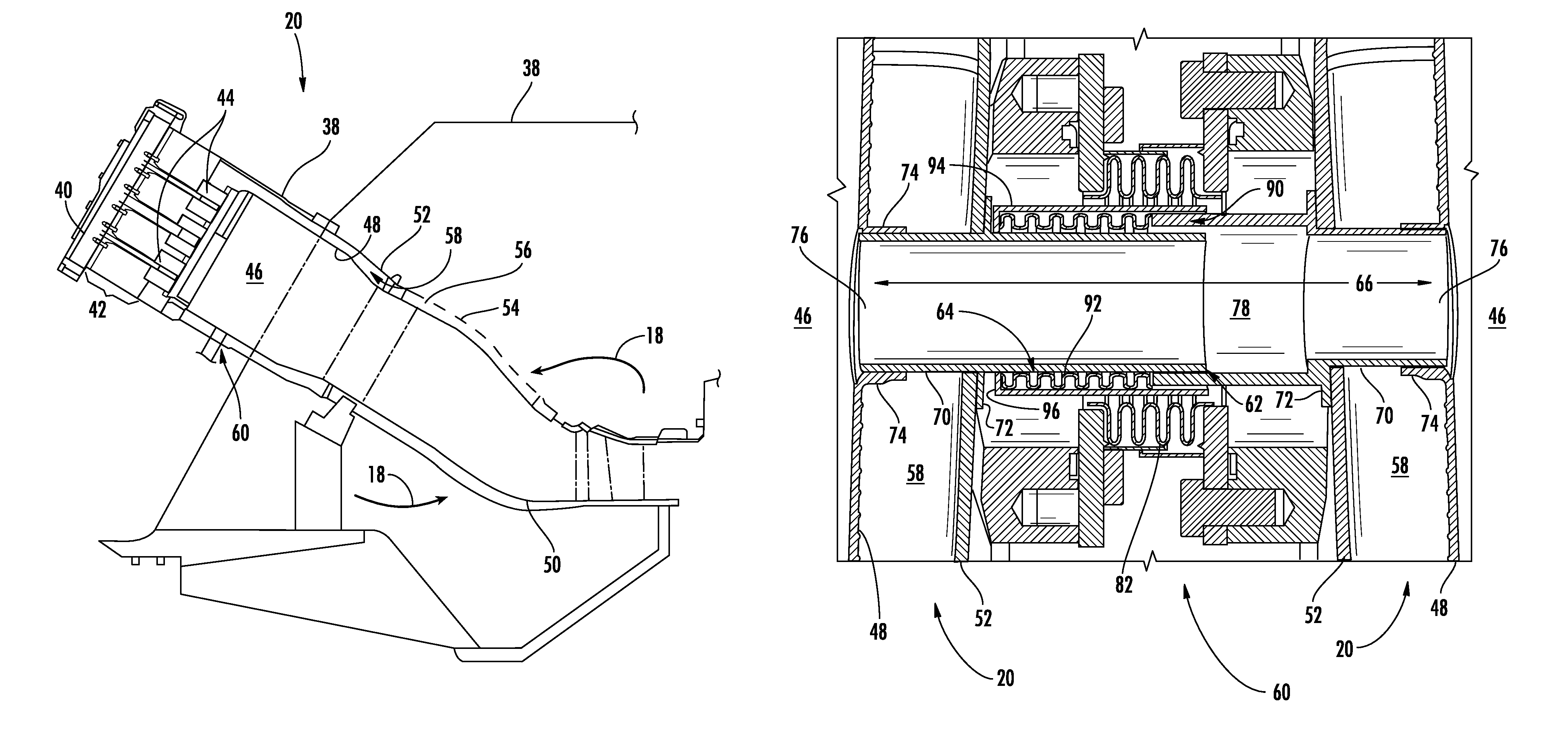
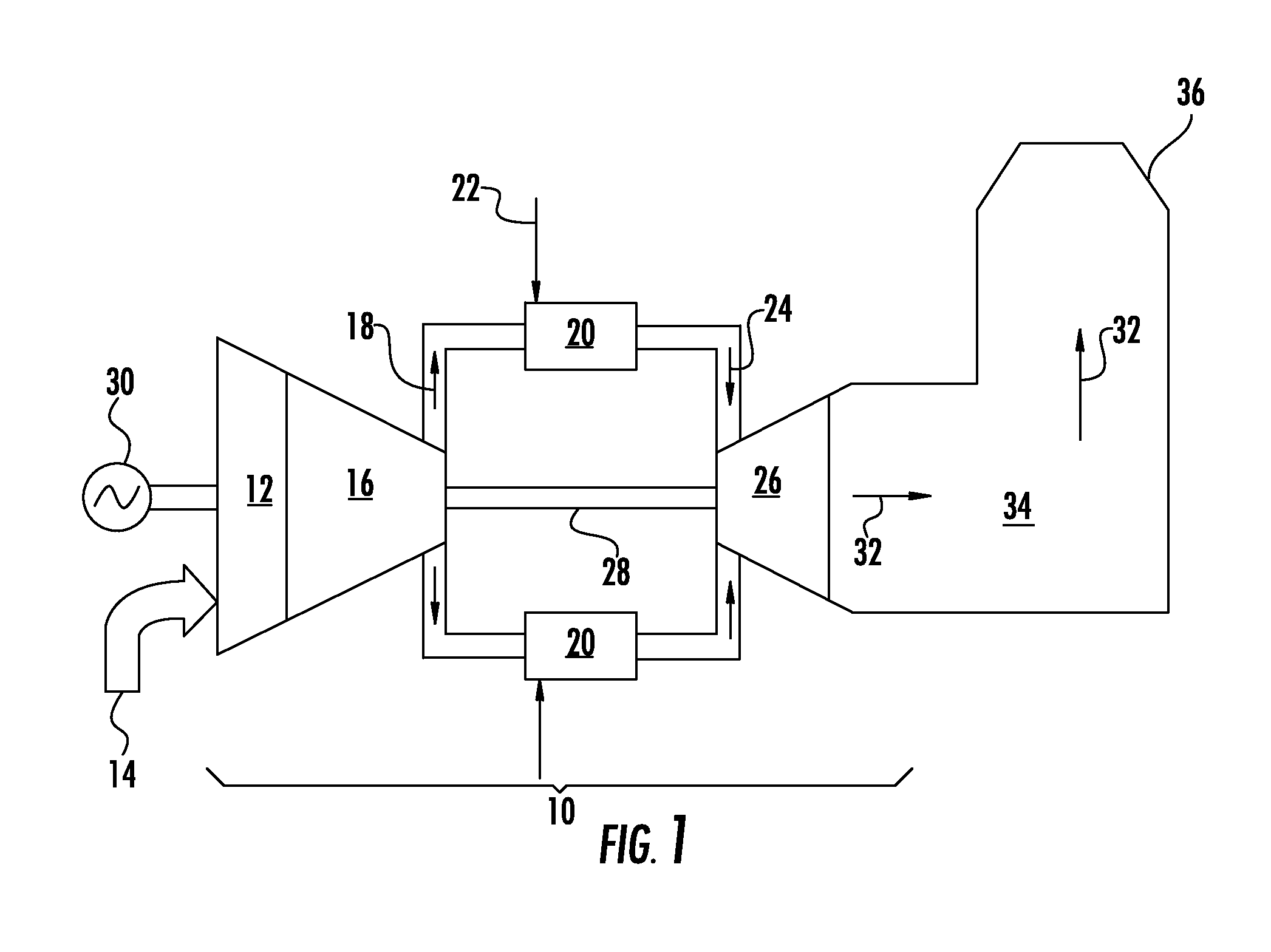
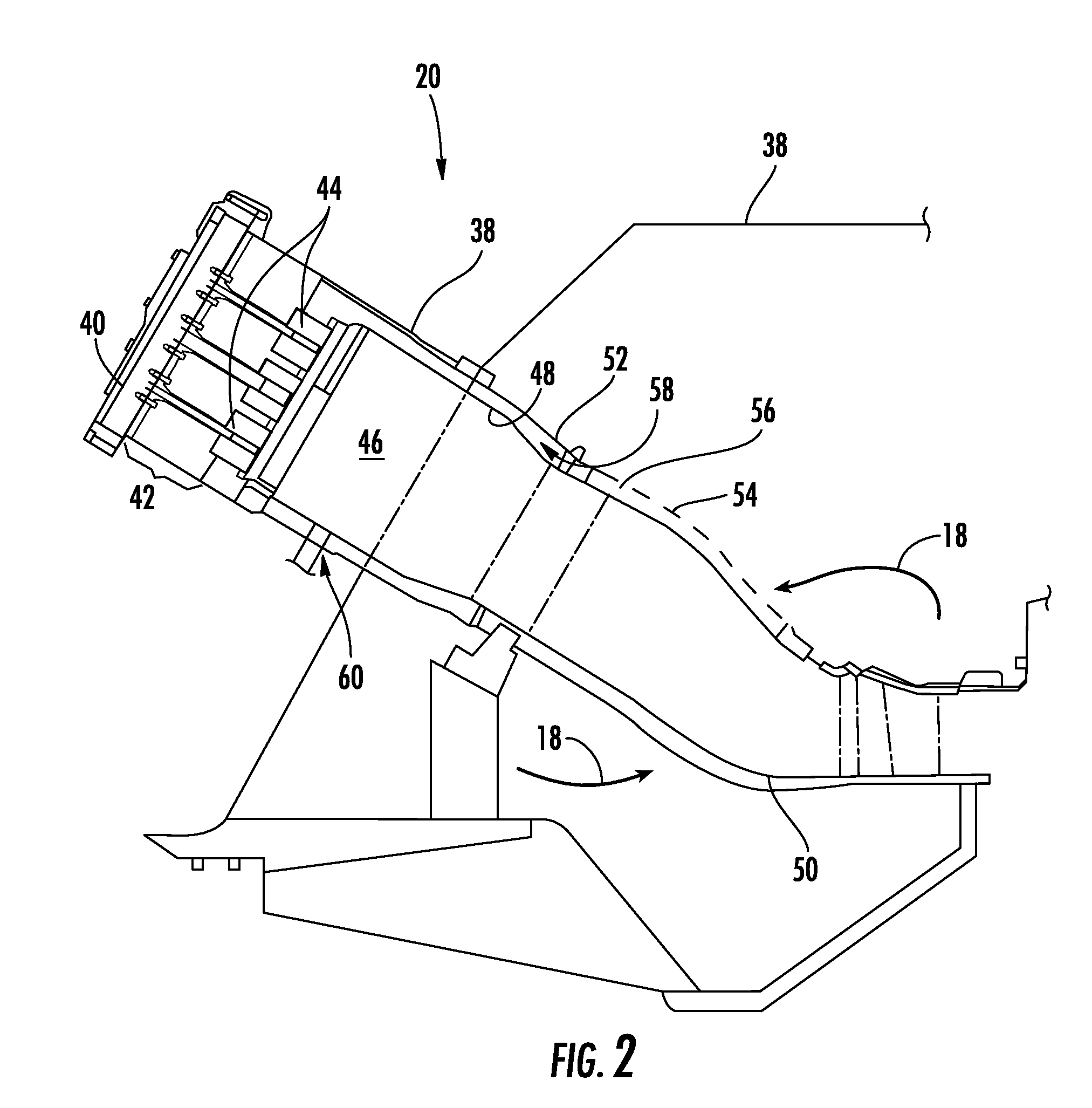
  • Crossfire tube assembly with tube bias between adjacent combustors
  • Crossfire tube assembly with tube bias between adjacent combustors
  • Crossfire tube assembly with tube bias between adjacent combustors

Examples


Embodiment Construction

[0016]Reference will now be made in detail to present embodiments of the invention, one or more examples of which are illustrated in the accompanying drawings. The detailed description uses numerical and letter designations to refer to features in the drawings. Like or similar designations in the drawings and description have been used to refer to like or similar parts of the invention. As used herein, the terms “first”, “second”, and “third” may be used interchangeably to distinguish one component from another and are not intended to signify location or importance of the individual components. The terms “upstream,”“downstream,”“radially,” and “axially” refer to the relative direction with respect to fluid flow in a fluid pathway. For example, “upstream” refers to the direction from which the fluid flows, and “downstream” refers to the direction to which the fluid flows. Similarly, “radially” refers to the relative direction substantially perpendicular to the fluid flow, and “axiall...


PUM


Abstract

A crossfire tube assembly between adjacent combustors includes a first sleeve adapted to provide fluid communication from a first combustor and a second sleeve adapted to connect to provide fluid communication from a second combustor. The second sleeve extends at least partially inside the first sleeve. A bias is between the first and second sleeves.

Description

FIELD OF THE INVENTION[0001]The present invention generally involves a crossfire tube assembly between adjacent combustors.BACKGROUND OF THE INVENTION[0002]Gas turbines are widely used in industrial and commercial operations. A typical gas turbine includes an inlet section, a compressor section, a combustion section, a turbine section, and an exhaust section. The inlet section cleans and conditions a working fluid (e.g., air) and supplies the working fluid to the compressor section. The compressor section increases the pressure of the working fluid and supplies a compressed working fluid to the combustion section. The combustion section mixes fuel with the compressed working fluid and ignites the mixture to generate combustion gases having a high temperature and pressure. The combustion gases flow to the turbine section where they expand to produce work. For example, expansion of the combustion gases in the turbine section may rotate a shaft connected to a generator to produce elect...

Claims


Application Information

Patent Timeline
Patent Type & Authority Patents(United States)
IPC IPC(8): F23R3/48
CPCF23R3/48
Inventor OVERBY, BRANDON TAYLORBELSOM, KEITH CLETUSALLEN, JONATHAN KAYBENSON, KYLE ERICMELTON, PATRICK BENEDICTDICINTIO, RICHARD MARTINSTOIA, LUCAS JOHNPENTECOST, RONNIE RAY
Owner GENERAL ELECTRIC CO
Features
  • R&D
  • Intellectual Property
  • Life Sciences
  • Materials
  • Tech Scout
  • Unparalleled Data Quality
  • Higher Quality Content
  • 60% Fewer Hallucinations
Learn More